background image

No.51878

AV21BT7ENS / AV21BT7ENB

AV21BT7EPS / AV21BT7EPB

AV21BT7EES / AV21BT7EEB

  5

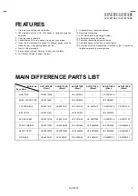
FEATURES

1.  It is a remte controlled color television.
2.  100 programmes from VHF, UHF bands or cable channels can

be preset.

3.  It can tune cable channels.
4.  Controlling the TV is very easy by its menu driven system.
5.  It has two Euroconnector sockets for external device (such as

video recorder, video games, audio set, etc.)

6.  Front AV Input available.
7.  Stereo sound systems ( Nicam) are available.
8.  Full function Teletext (Fastext, Toptext).

9.  It is possible to connect headphone.
10. Direct channel access.
11.  APS (Automatic Programming System).
12. All programmes can be named.
13. Forward or backward automatic tuning.
14. Automatic sound mute when no transmission.
15. 5 minutes after the broadcasting (closedown), the TV switches

itself automatically to stand-by mode.

MAIN DIFFERENCE PARTS LIST

MODEL No.

Parts Name

AV21BT7ENS

(Silver)

AV21BT7ENB

 (Black)

AV21BT7EPS

(Silver)

AV21BT7EPS

(Black)

AV21BT7EES

(Silver)

AV21BT7EEB

(Black)

MAIN PWB

VE-20073428

VE-20073414

VE-20073418

MULTI SOUND PWB

VE-20078991

VE-20079020

VE-20078991

F CARTON BOX

VE-20074161

VE-20074151

VE-20074143

VE-20074010

VE-20074030

VE-20074127

INST BOOK

VE-50021021

VE-50021022

VE-50021020

RATING LABEL

VE-20074158

VE-20074150

VE-20074142

VE-20077009

VE-20074129

VE-20074126

FRONT CABINET

VE-20073594

VE-20068238

VE-20073594

VE-20068238

VE-20073594

VE-20068238

REAR COVER

VE-20066509

VE-20079492

VE-20066509

VE-20079492

VE-20066509

VE-20079492

JVC MARK

VE-40009153

VE-40009151

VE-40009153

VE-40009151

VE-40009153

VE-40009151

Summary of Contents for AV21BT7EEB

Page 1: ...7ENB AV21BT7EPS AV21BT7EPB AV21BT7EES AV21BT7EEB CONTENTS SPECIFICATIONS 2 SAFETY PRECAUTIONS 4 FEATURES 5 MAIN DIFFERENCE PARTS LIST 5 SPECIFIC SERVICE INSTRUCTIONS 6 SERVICE ADJUSTMENTS 9 PARTS LIST 17 OPERATING INSTRUCTIONS STANDARD CIRCUIT DIAGRAM 2 1 SERVICE MANUAL COLOUR TELEVISION www DataSheet4U com www DataSheet4U com www DataSheet4U com ...

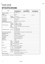
Page 2: ...MHz 32 9MHz 6 0MHz Intermediate Frequency SIF Carrier 33 4MHz 5 5MHz Colour Sub Carrier Frequency PAL 4 43MHz SECAM 4 43MHz NTSC 3 58MHz 4 43MHz Aerial Input Terminal 75Ohm Unbalanced Power Input AC 220 240V 50Hz Power Consumption 95W Max 73W Avg Stand by 5W Picture Tube 21 inch measured diagonally High Voltage 26kV in cut off service mode Speaker 57x160 mm oval type X 2 Audio Output 8 8W Video 1V...

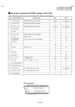
Page 3: ...e 3 AUDIO L output 500mVrms Nominal Low impedance TV OUT TV LINE OUT 4 AUDIO GND 5 GND B 6 AUDIO L input 500mVrms Nominal High impedance 7 B input 700mVB W 75Ω NC 8 FUNCTON SW SLOW SW Low 0 3V High 8 12V High impedance NC 9 GND G 10 NC 11 G input 700mVB W 75Ω NC 12 NC 13 GND R 14 GND YS NC 15 R C input R 700mVB W 75Ω C 300mVP P 75Ω R C only C 16 Ys input Low 0 0 4 High 1 3V 75Ω NC 17 GND VIDEO out...

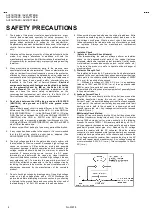
Page 4: ...ldering etc To maintain the proper minimum level of soft X Ray emission components in the high voltage circuitry including the picture tube must be the exact replacements or alternatives approved by the manufacturer of the complete product 7 Do not check high voltage by drawing an arc Use a high voltage meter or a high voltage probe with a VTVM Discharge the picture tube before attempting meter co...

Page 5: ...tic tuning 14 Automatic sound mute when no transmission 15 5 minutes after the broadcasting closedown the TV switches itself automatically to stand by mode MAIN DIFFERENCE PARTS LIST MODEL No Parts Name AV21BT7ENS Silver AV21BT7ENB Black AV21BT7EPS Silver AV21BT7EPS Black AV21BT7EES Silver AV21BT7EEB Black MAIN PWB VE 20073428 VE 20073414 VE 20073418 MULTI SOUND PWB VE 20078991 VE 20079020 VE 2007...

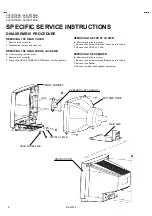
Page 6: ...ve the 1 screw B 2 After pulling HEAD PHONE JACK PWB back it shifts rightward REMOVING THE FRONT AV PWB z After removing the rear cover 1 Remove the 2 screws marked C as shown in the figure 2 Remove the FRONT AV PWB REMOVING THE SPEAKER z After removing the rear cover 1 Remove the 4 screws marked D as shown in the figure 2 Remove the speaker 3 Remove the other hand speaker same step FRONT CABINET ...

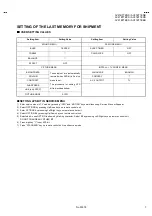
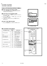
Page 7: ...ice menu is set The procedure for selling APS bit is discribed bellow PICTURE MODE AUTO SETTING APS BIT IN SERVICE MENU 1 Enter service menu in TV mode by pressing INFO and MUTING keys simultaneously Service Menu will appear 2 Select OPTIONS by pressing Up Down keys on remote control unit 3 Enter OPTIONS by presssing Left Right keys on remote control unit 4 Select OPTION 8 by pressing Up Down keys...

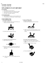
Page 8: ...each end 2 Shift with tweezers and remove the chip part Transistors diodes variable resistors etc 1 Apply extra solder to each lead 2 As shown in the figure push the part with tweezers and alternately melt the solder at each lead Shift and remove the chip part Note After removing the part remove remaining solder from the pattern 2 How to install Chip parts Resistors capacitors etc 1 Apply solder t...

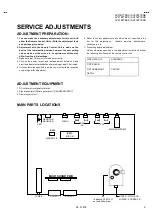
Page 9: ...r waiting at least 30 minutes 5 Unless otherwise specified prepare the most suitable reception or input signal for adjustment 6 Never touch any adjustment parts which are not specified in the list for this adjustment variable resistors transformers condensers etc 7 Presetting before adjustment Unless otherwise specified in the adjustment instructions preset the following functions with the remote ...

Page 10: ...ANDARD Key on REMOTE CONTROL UNIT ADJUSTMENT SERVICE MENU ADJUSTMENT ITEM ADJUST No DISCRIPTION 00 White Point RED 01 White Point GREEN WHITE BALANCE 02 White Point BLUE AGC 03 AGC IF PLL NEGATIVE 04 IF PLL Negative IF PLL POSITIVE 05 IF PLL Positive 06 Y Delay PAL 07 Y Delay SECAM LUMINANCE DELAY 08 Y Delay NTSC 12 4 3 PICTURE MODE 4 3 HORIZONTAL SHIFT 23 16 9 PICTURE MODE 13 4 3 PICTURE MODE VER...

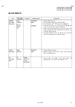
Page 11: ...y pressing 1 white bit 2 is blinking 5 Observe the thin horizontal blue white line in the middle of the screen and adjust the lower VR of the FBT until the line is in its thinnest visible thickness 6 Then make Option 02 bit 6 0 by pressing 0 on the remote control unit although you do not see any picture FOCUS Adjustment Signal generator FOCUS VR FBT 1 Receive a PAL circle pattern 2 Adjust the uppe...

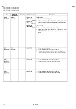
Page 12: ...eceive a white and black signal colour off 2 Adjust the Adjust 00 Adjust 01 Adjust 02 in the SERVICE MENU so that the whiteness in the screen become sharp AGC Adjustment DC voltmeter ADJUST 03 1 Receive a any broadcast 2 Select ADJUST 03 from SERVICE MENU 3 Connect a DC voltmeter to pin 1 of the tuner Change the AGC parameter until you see 3 70VDC on voltmeter display IF PLL NEGATIVE Adjustment AD...

Page 13: ... 3 Adjust Y Delay SECAM till the colour transients on the colour bar of the pattern become as sharper and colours between transients do not mix with each other as possible Note If the SAW filter is one of the G1965M K2958M K2962M G3957M K6256K or K6259K there is constant group delay distortion so for an equal delay of the luminance and chrominance signal the delay must be set at a value of 160nS T...

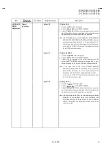
Page 14: ...s on both the upper and lower part of test pattern become equal to the squares laying on the vertical centre of the test pattern Check and readjust VERTICAL SLOPE item if the adjustment becomes improper after some other geometric adjustments are done 5 Set 16 9 aspect mode 6 Adjusts with the step which is the same above from 3 to 4 about the 16 9 aspect mode too VERTICAL AMPLITUDE Adjustment Signa...

Page 15: ...e 16 9 aspect mode too VERTICAL SHIFT Adjustment Signal generator Adjust 16 4 3 Adjust 27 16 9 1 Receive a PAL test pattern signal or the symmetrical signal in the top and the bottom and on either side to find 2 Set 4 3 aspect mode 3 Select ADJUST 15 from SERVICE MENU 4 Change Vertical Shift till the test pattern is vertically centred i e horizontal line at the centre pattern is in equal distance ...

Page 16: ...No 51878 AV21BT7ENS AV21BT7ENB AV21BT7EPS AV21BT7EPB AV21BT7EES AV21BT7EEB 16 MEMO ...

Reviews: