background image

No. 51881

AV28BT5ENS / AV28BT5ENB

AV28BT5EES / AV28BT5EEB

11

ADJUSTMENTS


Item

Measuring

instrument

Test point

Adjustment part

Description

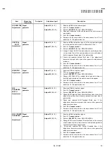
SCREEN
VOLTAGE
Adjustment

Signal
Generator

Remote
Control
unit

SCREEN VR
[FBT]

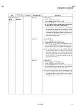
OPTION 02

1. Receive 

PAL

 colour bar.

2.  Enter the Option settings in the SERVICE MENU.
3.  Press the function 


/


 key, and Enter 

Option 02

.

4.  To change bit 6, come on to it by using function    /    and

make it “1” by pressing “1” white bit 2 is blinking.

5.  Observe the thin horizontal blue-white line in the middle of the

screen, and adjust the lower VR of the FBT, until the line is in
its thinnest visible thickness.

6.  Then make Option 02 bit 6 “0” , by pressing “0” on the remote

control unit, although you do not see any picture.

FOCUS
Adjustment

Signal
generator

FOCUS VR
[FBT]

1. Receive 

PAL

 circle pattern.

2.  Adjust the upper VR of the FBT, until you get the Optinum

focus, the sharpest picture.

B1
VOLTAGE
check

DC
Voltmeter

Marked

[150/115V]
on the
MAIN PWB

1.  Check whether the voltage at the point named and silk

screened as “150 / 115V” on the MAIN PWB is 150V DC.

Summary of Contents for AV28BT5EEB

Page 1: ...AV28BT5EES AV28BT5EEB CONTENTS SPECIFICATIONS 2 SAFETY PRECAUTIONS 4 FEATURES 5 MAIN DIFFERENCE PARTS LIST 5 SPECIFIC SERVICE INSTRUCTIONS 6 SERVICE ADJUSTMENTS 9 PARTS LIST 17 OPERATING INSTRUCTIONS STANDARD CIRCUIT DIAGRAM 2 1 SERVICE MANUAL COLOUR TELEVISION www DataSheet4U com www DataSheet4U com DataSheet www DataSheet4U com ...

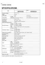
Page 2: ...z 6 0MHz Intermediate Frequency SIF Carrier 33 4MHz 5 5MHz Colour Sub Carrier Frequency PAL 4 43MHz SECAM 4 43MHz NTSC 3 58MHz 4 43MHz Aerial Input Terminal 75Ohm Unbalanced Power Input AC 170 270V Power Consumption 126W Max 103W Avg Stand by 5W Picture Tube 28 inch measured diagonally High Voltage 28kV in cut off service mode Speaker 101 mm round type X 2 Audio Output 8W 8W Video 1Vp p 75 Ohm S V...

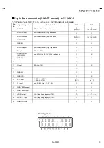
Page 3: ... output 500mVrms Nominal Low impedance TV OUT TV LINE OUT 4 AUDIO GND 5 GND B 6 AUDIO L input 500mVrms Nominal High impedance 7 B input 700mVB W 75Ω NC 8 FUNCTON SW SLOW SW Low 0 3V High 8 12V High impedance NC 9 GND G 10 NC 11 G input 700mVB W 75Ω NC 12 NC 13 GND R 14 GND YS NC 15 R C input R 700mVB W 75Ω C 300mVP P 75Ω R C only C 16 Ys input Low 0 0 4 High 1 3V 75Ω NC 17 GND VIDEO output 18 GND ...

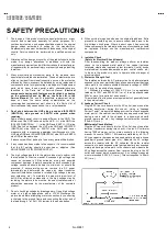
Page 4: ... To maintain the proper minimum level of soft X Ray emission components in the high voltage circuitry including the picture tube must be the exact replacements or alternatives approved by the manufacturer of the complete product 7 Do not check high voltage by drawing an arc Use a high voltage meter or a high voltage probe with a VTVM Discharge the picture tube before attempting meter connection by...

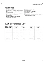
Page 5: ...nect headphone 10 Direct channel access 11 APS Automatic Programming System 12 All programs can be named 13 Forward or backward automatic tuning 14 Automatic sound mute when no transmission 15 5 minutes after the broadcasting closedown the TV switches itself automatically to stand by mode MAIN DIFFERENCE LIST MODEL No Parts Name AV28BT5ENS Silver AV28BT5ENB Black AV28BT5EES Silver AV28BT5EEB Black...

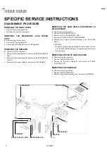
Page 6: ...REMOVING THE MAIN PWB PROCEDURE TO DEVELOPMENT z After removing the rear cover 1 Remove the JACK BOARD ASS Y 2 Remove the LEFT SPEAKER BKT ASS Y 3 Remove the POWER SUPPLY TRANSFORMER 4 Remove the 2 screws marked F atached to the MAIN PWB ASS Y CAUTIONS Be careful enough when developing a main chassis The wire of a POWER TRANSFER does not separate and short circuit with other parts REMOVING THE FRO...

Page 7: ...s set The procedure for selling APS bit is discribed bellow PICTURE MODE AUTO SETTING APS BIT IN SERVICE MENU 1 Enter service menu in TV mode by pressing INFO and MUTING keys simultaneously Service Menu will appear 2 Select OPTIONS by pressing Up Down keys on remote control unit 3 Enter OPTIONS by pressing Left Right keys on remote control unit 4 Select OPTION 8 by pressing Up Down keys on remote ...

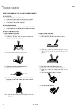
Page 8: ...Shift with tweezers and remove the chip part Transistors diodes variable resistors etc 1 Apply extra solder to each lead 2 As shown in the figure push the part with tweezers and alternately melt the solder at each lead Shift and remove the chip part Note After removing the part remove remaining solder from the pattern 2 How to install Chip parts Resistors capacitors etc 1 Apply solder to the patte...

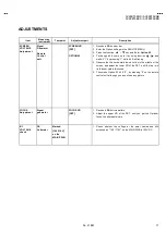
Page 9: ...t 30 minutes 5 Unless otherwise specified prepare the most suitable reception or input signal for adjustment 6 Never touch any adjustment parts which are not specified in the list for this adjustment variable resistors transformers condensers etc 7 Presetting before adjustment Unless otherwise specified in the adjustment instructions preset the following functions with the remote control unit VIDE...

Page 10: ...5 IF PLL Positive 06 Y Delay PAL 07 Y Delay SECAM LUMINANCE DELAY 08 Y Delay NTSC 10 4 3 PICTURE MODE VERTICAL ZOOM 21 16 9 PICTURE MODE 11 4 3 PICTURE MODE VERTICAL SCROLL 22 16 9 PICTURE MODE 12 4 3 PICTURE MODE 4 3 HORIZONTAL SHIFT 23 16 9 PICTURE MODE 13 4 3 PICTURE MODE VERTICAL SLOPE 24 16 9 PICTURE MODE 14 4 3 PICTURE MODE VERTICAL AMPLITUD 25 16 9 PICTURE MODE 15 4 3 PICTURE MODE S CORRECT...

Page 11: ...hite bit 2 is blinking 5 Observe the thin horizontal blue white line in the middle of the screen and adjust the lower VR of the FBT until the line is in its thinnest visible thickness 6 Then make Option 02 bit 6 0 by pressing 0 on the remote control unit although you do not see any picture FOCUS Adjustment Signal generator FOCUS VR FBT 1 Receive a PAL circle pattern 2 Adjust the upper VR of the FB...

Page 12: ...ite and black signal colour off 2 Adjust the Adjust 00 Adjust 01 Adjust 02 in the SERVICE MENU so that the whiteness in the screen become sharp AGC Adjustment DC voltmeter ADJUST 03 1 Receive a any broadcast 2 Select ADJUST 03 from SERVICE MENU 3 Connect a DC voltmeter to pin 1 of the tuner Change the AGC parameter until you see 3 70VDC on voltmeter display IF PLL NEGATIVE Adjustment ADJUST 04 1 S...

Page 13: ... Delay SECAM till the colour transients on the colour bar of the pattern become as sharper and colours between transients do not mix with each other as possible Note If the SAW filter is one of the G1965M K2958M K2962M G3957M K6256K or K6259K there is constant group delay distortion so for an equal delay of the luminance and chrominance signal the delay must be set at a value of 160nS This means t...

Page 14: ... adjustment is correct after completing Service Mode Adjustment 5 Set 16 9 aspect mode 6 Adjusts with the step which is the same above from 3 to 4 about the 16 9 aspect mode too VERTICAL SLOPE Adjustment Signal generator Adjust 13 4 3 Adjust 24 16 9 1 Receive a CROSS HATCH signal 2 Set 4 3 aspect mode 3 Select ADJUST 13 from SERVICE MENU 4 Change vertical slope till the size of squares on both the...

Page 15: ...attern signal 2 Set 4 3 aspect mode 3 Select ADJUST 17 from SERVICE MENU 4 Change EW Width till the vertical black and white bars on both left and right side of the pattern exactly disappear 5 Set 16 9 aspect mode 6 Adjusts with the step which is the same above from 3 to 4 about the 16 9 aspect mode too EW PARABOLA WIDTH Adjustment Signal generator Adjust 18 4 3 Adjust 29 16 9 1 Receive a PAL test...

Page 16: ...t 4 3 aspect mode 3 Select ADJUST 15 from SERVICE MENU 4 Change EW Trapezium till vertical lines especially lines at the sides of the picture frame became parallel to the both sides of picture tube as possible 5 Check and readjust EW Trapezium item if the adjustment becomes improper after some other geometric adjustment 6 Set 16 9 aspect mode 7 Adjusts with the step which is the same above from 3 ...

Page 17: ...4 VP 0112 DP205180 VICTOR COMPANY OF JAPAN LIMITED HOME AV NETWORK BUSINESS UNIT 12 3 chome Moriya cho Kanagawa ku Yokohama Kanagawa prefecture 221 8528 Japan ...

Reviews: