No. 51944
AV28CH1EUS
AV28CH1EUB
28
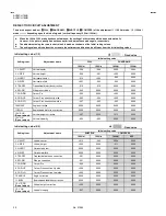
Item
Measuring
instrument
Test point
Ad justment part
Description
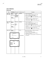
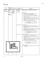
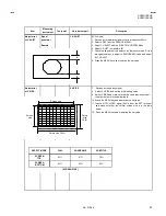
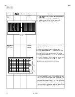
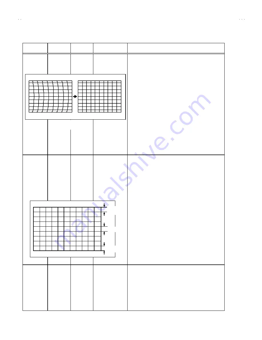
Ad justment of
BOW
11.BOW
•
In case where there is a bow-shaped distortion of images on the
screen. (Fig.B)
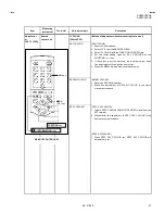
43. Select 11.BOWwith the FUNCTION UP/DOWN key.
44. Adjust BOW, and bring the VERTICAL lines straight.
45. Press the MENU key and memoriz e the s et value.
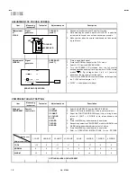
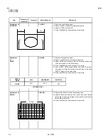
Ad justment of
V-S.CR&
V.LINEARITY
12.V-S.CR
13.V-LIN
•
When the vertical linearity has been deteriorated remarkably,
perform the following steps.
46. Receive a cross -hatc h signal.
47. Select 13.V-LIN with the FUNCTION UP/DOW N k ey.
48. Set the initial setting value of 13.V-LIN with the FUNCTION
- / + key.
49. Select 12.V-S.COR with the FUNCTION UP / DOWN key.
50. Set the initial s etting value of 12.V-S.COR with the FUNCTION
- / + key.
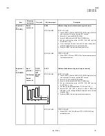
51. Adjust 13.V-LIN and 12.V-S.COR so that the spac es of each
line on TOP, CENTER and BOTTOM bec ome uniform.
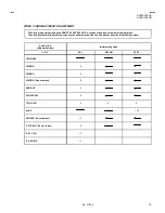
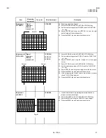
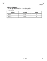
NOTE
:
Do not adjust PANORAMIC & SUBTITLE mode.
At first the adjustment in 100Hz FULL mode should be done,
then the data for the other aspect mode is corrected in the
respective value at the s ame time. And confirm the deflection
adjustment initial setting value in 120Hz (NTSC EXT mode)
FULL mode. If the adjustment in 100Hz eac h aspect mode has
been done and stored, the data for the s ame as pect modes in
120Hz is corrected in the res pective value. Only the data for the
other as pect mode in 120Hz is corrected for its elf.
CENTER
BOT TOM
TOP
Fig. B