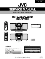


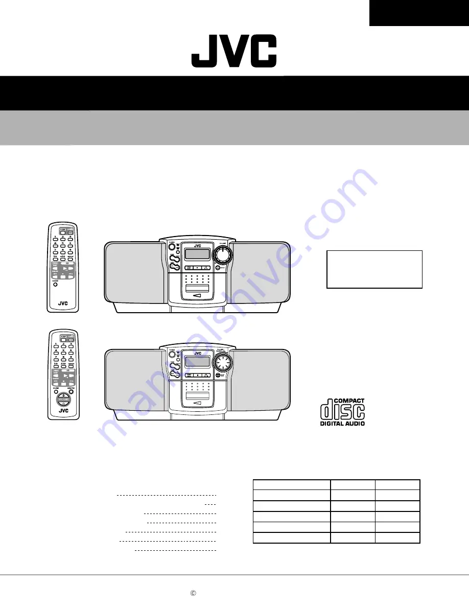
SERVICE MANUAL
CD PORTABLE SYSTEM
No.20819
July. 2000
Printed in Japan
200007(S)
RC-BZ5LB/BZ5RD
RC-BZ6BU
(No.20819)
RC-BZ5LB/BZ5RD
RC-BZ6BU
Safety precautions
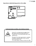
Importance administering point on the safety
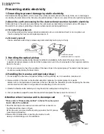
Preventing static electricity
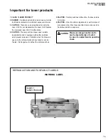
Important for laser products
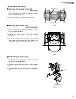
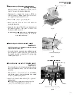
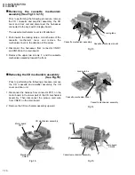
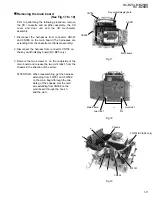
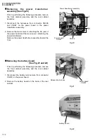
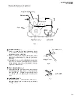
Disassembly method
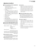
Adjustment method
Description of major ICs
RC-BZ5LB/BZ5RD
REMOTE CONTROL RM-SRCBZ5
REMOTE CONTROL RM-SRCBZ6
RC-BZ6BU
RC-BZ5LB/BZ5RD
RC-BZ6BU
Areas suffix
J ---------------- U.S.A.
C ------------- Canada
VICTOR COMPANY OF JAPAN, LIMITED
AUDIO & COMMUNICATION BUSINSS DIVISION
PERSONAL & MOBILE NETWORK B.U. 10-1,1Chome,Ohwatari-machi,Maebashi-city,371-8543,Japan
COPYRIGHT 2000 VICTOR COMPANY OF JAPAN, LTD.
1-2
1-3
1-4
1-5
1-6
1-15
1-18
Contents
Comparison table
Item
RC-BZ5LB/BZ5RD RC-BZ6BU
Jog dial circuit
Not used
Used
Back light (LCD)
Not used
Used
Bass boost circuit
Not used
Used
Power amplifier
14W
18W
Electrical volume
Not used
Used


