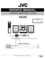
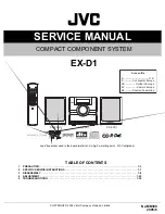
background image

SERVICE MANUAL

COPYRIGHT © 2005 Victor Company of Japan, Limited

No.MB399

2005/6

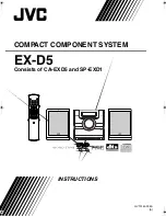
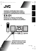
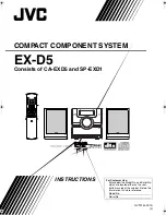
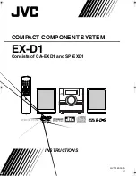
COMPACT COMPONENT SYSTEM

MB399

2005

6

EX-D1

Lead free solder used in the board (material : Sn-Ag-Cu, melting point : 219 Centigrade)

TABLE OF CONTENTS

1

PRECAUTION. . . . . . . . . . . . . . . . . . . . . . . . . . . . . . . . . . . . . . . . . . . . . . . . . . . . . . . . . . . . . . . . . . . . . . . . .  1-3

2

SPECIFIC SERVICE INSTRUCTIONS . . . . . . . . . . . . . . . . . . . . . . . . . . . . . . . . . . . . . . . . . . . . . . . . . . . . . .  1-7

3

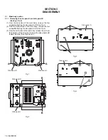
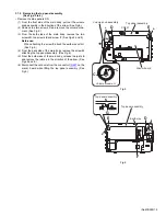
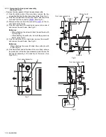
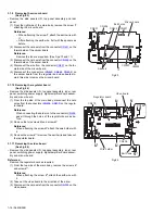
DISASSEMBLY  . . . . . . . . . . . . . . . . . . . . . . . . . . . . . . . . . . . . . . . . . . . . . . . . . . . . . . . . . . . . . . . . . . . . . . .  1-8

4

ADJUSTMENT . . . . . . . . . . . . . . . . . . . . . . . . . . . . . . . . . . . . . . . . . . . . . . . . . . . . . . . . . . . . . . . . . . . . . . .  1-25

5

TROUBLESHOOTING . . . . . . . . . . . . . . . . . . . . . . . . . . . . . . . . . . . . . . . . . . . . . . . . . . . . . . . . . . . . . . . . .  1-35

CA-EXD1

SP-EXD1

SP-EXD1

Area suffix

B ------------------------------ U.K.
E ---------- Continental Europe
EN ----------- Northern Europe
EV ------------- Eastern Europe
EE -------- Russian Federation

Summary of Contents for CA-EXD1

Page 1: ...free solder used in the board material Sn Ag Cu melting point 219 Centigrade TABLE OF CONTENTS 1 PRECAUTION 1 3 2 SPECIFIC SERVICE INSTRUCTIONS 1 7 3 DISASSEMBLY 1 8 4 ADJUSTMENT 1 25 5 TROUBLESHOOTING 1 35 CA EXD1 SP EXD1 SP EXD1 Area suffix B U K E Continental Europe EN Northern Europe EV Eastern Europe EE Russian Federation ...

Page 2: ...nization negative PB PR output 0 7 V p p 75 Ω Audio output Analog sound output Speakers 2 Output power IEC 268 3 36 W 18 W 18 W at 4 Ω 10 THD Fitting impedance 4 Ω to 16 Ω Headphones 1 11 mW 32 Ω Fitting impedance 16 Ω to 1 kΩ Subwoofer 1 500 mVrms 10 kΩ Digital sound output Optical 1 21 dBm to 15 dBm Audio input Sound input AUX 1 400 mV 50 kΩ USB AUDIO 1 Tuner FM tuner Receiving frequency 87 50 M...

Page 3: ...ack control shafts etc to be sure the product is safe to operate without danger of electrical shock Do not use a line isolation transformer during this check Plug the AC line cord directly into the AC outlet Using a Leakage Current Tester measure the leakage current from each exposed metal parts of the cabinet particular ly any exposed metal part having a return path to the chassis to a known good...

Page 4: ...same safety characteristics as the recommended replacement parts shown in the Parts List of the Service Manual and may create shock fire or other hazards 4 The leads in the products are routed and dressed with ties clamps tubings barriers and the like to be separated from live parts high temperature parts moving parts and or sharp edges for the prevention of electric shock and fire hazard When ser...

Page 5: ...n the optical pickup The tester s internal power source can easily destroy the laser diode 1 7 Handling the traverse unit optical pickup 1 Do not subject the traverse unit optical pickup to strong shocks as it is a sensitive complex unit 2 Cut off the shorted part of the flexible cable using nippers etc after replacing the optical pickup For specific details refer to the replacement procedure in t...

Page 6: ...lock failed or defeated AVOID DIRECT EXPOSURE TO BEAM e VARNING Synlig och osynling laserstrålning när den öppnas och spärren är urkopplad Betrakta ej strålen s VARO Avattaessajasuojalukitus ohitettuna tai viallisena olet alttiina näkyvälle ja näkymättömälle lasersäteilylle Vältä säteen kohdistumista suoraan itseesi f ADVARSEL Synlig og usynlig laserstråling når maskinen er åben eller interlocken ...

Page 7: ... No MB399 1 7 SECTION 2 SPECIFIC SERVICE INSTRUCTIONS This service manual does not describe SPECIFIC SERVICE INSTRUCTIONS ...

Page 8: ...ide panels L R See Fig 1 2 From the bottom side of the main body remove the four screws B attaching the side panels L R See Fig 2 3 From the both sides of the main body release the joint a in the direction of the arrow and remove the side panels L R toward this side See Figs 3 and 4 Fig 1 Fig 2 Fig 3 Fig 4 A A Side panel R Side panel L B B Side panel R Side panel L Side panel R a a Side panel L a ...

Page 9: ...eference When attaching the screw F attach the earth wire with it See Fig 6 4 From the back side of the main body remove the screw G attaching the top panel assembly See Fig 6 5 From the both sides of the main body release the joints b and remove the joints c in the direction of the arrow See Figs 5 and 6 6 Disconnect the card wire from the connector CN427 on the micom board while lifting the top ...

Page 10: ... the earth wire See Fig 8 Reference When attaching the screw J attach the earth wire with it See Fig 8 After attaching the earth wire fix it with the spacers as before See Fig 8 5 From the left side of the main body remove the screw K and remove the earth wire See Fig 9 Reference When attaching the screw K attach the earth wire with it See Fig 9 6 From the bottom and both sides of the main body re...

Page 11: ...ve the side panels L R and top panel assembly 1 From the back side of the main body remove the two screws M attaching the tuner to the rear panel See Fig 10 2 Disconnect the card wire from the connector CN1 on the tuner See Fig 11 Fig 10 Fig 11 M M Tuner Tuner CN1 ...

Page 12: ...f the main body remove the ten screws N and screw P attaching the rear panel 2 From the top side of the main body disconnect the earth wire from the rear panel in the direction of the arrow 3 From the both sides of the main body release the joints f and remove the rear panel Fig 12 N N P N Rear panel f f Rear panel Earth wire N ...

Page 13: ...nels L R top panel assembly and rear panel 1 From the top side of the main body disconnect the wire from the connector CN200 on the regulator board See Fig 13 2 Take out the switching power supply in the direction of the arrow See Fig 14 Fig 13 Fig 14 Regulator board CN200 Switching power supply ...

Page 14: ... assembly See Fig 15 2 From the left side of the main body disconnect the connec tors CN310 CN311 CN312 on the digital amplifier board assembly from the regulator board See Fig 16 3 Release the joint g of the shield case B in the direction of the arrow and take out the digital amplifier board assembly from the main body See Fig 16 Fig 15 Fig 16 Digital amplifier board assembly Q Digital amplifier ...

Page 15: ... sink in the direction of the arrow See Figs 18 to 21 4 From the forward side of the digital amplifier board remove the screw S attaching the heat sink See Fig 22 5 Remove the solders from the soldered sections n p and bend the sections q r of the shield case A in the direction of the arrow See Fig 22 6 Take out the digital amplifier board from the shield case A Fig 17 Fig 18 Fig 19 Fig 20 Fig 21 ...

Page 16: ...er supply digital amplifier board assem bly and micom board 1 From the top side of the main body disconnect the card wires from the connectors CN208 CN210 on the regula tor board Reference When connecting the card wire to the connector CN208 pass it through the hole s of the regulator board as be fore 2 Remove the two screws U and screw U Reference When attaching the screw U attach the wire holder...

Page 17: ...ut the metal chassis See Fig 26 Reference When attaching the metal chassis pass the card wire through the hole t on the metal chassis as before 3 Disconnect the card wire from the connector CN703 on the video board See Fig 27 4 Remove the screw Y and take out the DVD mechanism as sembly from the bottom chassis See Fig 27 Reference When the resolution of DVD mechanism assembly is done se quentially...

Page 18: ...take out the front board 3 1 15 Removing the FL board See Fig 30 Remove the side panels L R top panel assembly front panel assembly and front board Remove the two screws AA and take out the FL board 3 1 16 Removing the headphone and USB board See Fig 30 Remove the side panels L R top panel and front panel assem blies 1 Remove the four screws AA and take out the support boards 2 Take out the headph...

Page 19: ... it from the projections a of the DVD mechanism assembly 3 Slide the clamper base in the direction of the arrow and re move it from the joints b Fig 1 3 2 2 Removing the tray assembly See Fig 2 1 From the top side of the DVD mechanism assembly re move the two screws B attaching the shaft guide of the tray assembly 2 Remove the tray assembly from the projections c of the DVD mechanism assembly and ...

Page 20: ...ire from the connector CN101 on the DVD module board If the card wire is discon nected without attaching solder the pickup may be de stroyed by static electricity See Figs 4 and 5 When attaching the DVD module board be sure to re move solders from the short land sections d after con necting the card wire to the connector CN101 on the DVD module board See Figs 4 and 5 3 Disconnect the card wire fro...

Page 21: ...pickup See Figs 4 and 6 3 Remove the screw E attaching the plate and thrust spring See Fig 6 4 Remove the engagement section h attaching the plate to the feed holder and remove the plate See Fig 6 5 Remove the engagement sections i j remove the thrust spring See Fig 6 6 Remove the shaft of the pickup from the section k on the traverse mechanism assembly and remove the shaft from the section m whil...

Page 22: ... m of the traverse mechanism assem bly See Fig 7 Note When attaching the shaft to the section m attach it under the torsion spring See Fig 7 3 Attach the plate and thrust spring See Fig 6 4 Remove solders from the short land sections d after con necting the card wire to the connector on the pickup See Figs 4 and 6 5 Turn the feed gear M in the direction of the arrow 1 to move the pickup in the dir...

Page 23: ...gear E and feed gear M at the same time after removing the three screws H attaching the feed holder See Fig 11 6 From the side of the feed holder remove the two screws J attaching the feed motor See Fig 12 3 2 8 Removing the spindle motor board See Figs 11 and 13 Remove the traverse mechanism assembly and DVD module board 1 From the top side of the traverse mechanism assembly re move the wires fro...

Page 24: ...Removing the motor See Figs 14 and 15 Remove the clamper base and tray assembly 1 From the bottom side of the DVD mechanism assembly re move the wires from the soldered section u on the switch board See Fig 14 2 From the top side of the DVD mechanism assembly re move the belt from the motor pulley See Fig 15 Note Take care not to attach grease on the belt 3 Remove the two screws M attaching the mo...

Page 25: ...der mecha is locked EJECT processing isn t done by pushing EJECT key at tray lock on state Then display to LOCKED UNLOCKED EJECT is pushed pushing STOP again tray lock is off Back up to tray locked ON OFF Press the EJECT button while pressing the STOP button on the main unit in standby mode LOCKED FL indication Press the EJECT button while pressing the STOP button again on the main unit in standby...

Page 26: ...U UY EE UF 1 To enter DVD TEST mode 1 AC POWER ON while holding PLAY PAUSE keys 2 DVD Mecha will start in TEST MODE FL will display 2 To exit DVD TEST mode During TEST MODE except for Device Key write DVD Region Re write press POWER KEY To exit TEST mode for Device Key Write DVD Region Re write first AC OFF then AC ON again to return to normal state 3 EEPROM INITIALIZATION 3 1 NORMAL INITIALIZE 1 ...

Page 27: ...ation After 2 seconds xxxxyyyy Light up DVD_LD and display laser current Press the 6 key on the remote controller JITX1 FL indication FL indication After 2 seconds xxxxyyyy Enter DVD x 2 JITTER MEASUREMENT MODE Press the 7 key on the remote controller EEP BWD FL indication FL indication After 2 seconds xxxxyyyy View EEPROM MECHA content in 1 address step Press the 8 key on the remote controller EE...

Page 28: ...M MECHA Press the PLAY key on the remote controller LSR JIT FL indication FL indication After 2 seconds xxxxyyyy Start PLAYING and obtain LASER CURRENT and JITTER value xxxxyyyy FL indication Stop JITTER measurement Press the STOP key on the remote controller Press the MENU key on the remote controller Return to starting screen of DVD test mode Press the STANDBY ON button on the main unit DVD chec...

Page 29: ...S G M M G G G U T 3 E E 2 1 1 2 1 2 D O N N 3 3 3 I P T U U T T T T O 4 0 1 4 1 4 8 DVD AUDIO STOP PLAY TOP MENU MENU PLAY SEARCH 10 KEY INPUT GROUP 10 KEY INPUT 1 5 1 5 5 1 O P E N 2 OPEN DVD Other source Under tray OPEN operation and OPEN state The last source is displayed C L O S E 3 CLOSE DVD Other source Under tray CLOSE operation The last source is displayed N O D I S C 4 NO DISC DVD Other s...

Page 30: ...1 G R R A I E T 1 T 1 T T 1 T 1 T 0 0 0 O T 0 N 1 O S S 1 M M 1 1 1 1 1 G D N U T 5 E E 2 2 2 2 2 2 2 2 0 0 0 R 1 0 O 2 M O N N 3 3 3 3 0 0 0 A 1 M 3 E E P C U U C C C C C M C R 4 1 4 1 1 4 1 4 1 0 0 0 2 4 R UNDER FL DISPLAY MODE UNDER FL DISPLAY MODE UNDER FL DISPLAY MODE UNDER FL DISPLAY MODE UNDER FL DISPLAY MODE Blink display ON 0 5s OFF 0 5s UNDER FL DISPLAY MODE Blink display ON 0 5s OFF 0 5...

Page 31: ...BC DISC PLAY NORMAL SEARCH NORMAL 10 KEY INPUT PROGRAM NO ENTRY PROGRAM STOP PROGRAM PLAY RANDOM STOP RANDOM SEARCH RANDOM PLAY PAUSE REPEAT ALL REPEAT 1 REPEAT A B RESUME 2 3 3 3 3 3 3 3 3 C C C C C C P C C C C D D D D D D D D D D 1 1 R x P 1 1 1 1 1 2 1 1 A x 1 R N O D G 4 O R 8 0 0 M 0 A T 1 0 0 0 M 1 2 2 2 2 2 2 2 Total time is displayed After 4 seconds EACH displays Blink display ON 0 5s OFF ...

Page 32: ...1 1 1 1 M 1 1 1 M 0 2 4 2 4 1 4 2 4 4 2 2 0 2 4 2 4 1 4 2 4 4 2 2 The light is always switched on at the time of MP3 UNDER FL DISPLAY MODE Blink display ON 0 5s OFF 0 5s UNDER FL DISPLAY MODE Blink display ON 0 5s OFF 0 5s UNDER FL DISPLAY MODE 12 MP3 STOP PLAY SEARCH 10 KEY INPUT GROUP 10 KEY INPUT REPEAT ALL REPEAT 1 PROGRAM NO ENTRY PROGRAM STOP PROGRAM PLAY RANDOM STOP RANDOM SEARCH RANDOM PLA...

Page 33: ...F 0 5s Blink display ON 0 5s OFF 0 5s UNDER FL DISPLAY MODE Blink display ON 0 5s OFF 0 5s Blink display ON 0 5s OFF 0 5s JPEG Under a display 10 KEY INPUT GROUP 10 KEY INPUT MPEG4 STOP PLAY SEARCH 10 KEY INPUT GROUP 10 KEY INPUT REPEAT ALL REPEAT 1 PROGRAM NO ENTRY PROGRAM STOP PROGRAM PLAY RANDOM STOP RANDOM SEARCH RANDOM PLAY PAUSE 3 3 0 3 5 3 5 5 3 5 5 1 3 3 Note P I R N P N O T A U T G N S P ...

Page 34: ...t FADE MUTING After cancel return to nomal display 2 MUTING V O L U M E 2 0 It displays for 5 seconds It returns to a normal display after 5 seconds 3 VOLUME UP DOWN S S L L E E E E P P 1 5 O 0 F m F i It displays for 5 seconds It returns to a normal display after 5 seconds 4 SLEEP n D D A D I I U I M M T M M M O M E E E R R D R I M O 1 2 M F AT PRESS DIMMER KEY REMOCON 5 SECOND INDICATE 5 DIMMER ...

Page 35: ...DS station with the select PTY code is found The found PTY code will blink for 8 seconds 0 5sec ON OFF Then display shows the PRESET RDS station for 1 sec Then display PS information IF CANNOT FOUND DISPLAY NOT FOUND FOR 2 SEC RETURN TO PREVOUS DISPLAY 10 FL display Function No PTY SELECTION S S X S U B W O O F O F F E R It displays for 5 seconds It returns to a normal display after 5 seconds It d...

Page 36: ... No MB399 AV MULTIMEDIA COMPANY AUDIO VIDEO SYSTEMS CATEGORY 10 1 1chome Ohwatari machi Maebashi city 371 8543 Japan Victor Company of Japan Limited VPT Printed in Japan ...

Reviews: