1-10 (No.MB399)
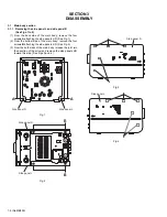
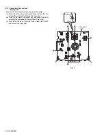
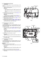
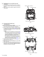
3.1.3 Removing the front panel assembly
(See Figs.7 to 9)
• Remove the side panels L/R and top panel assembly.
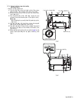
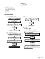
(1) From the bottom side of the main body, remove the two
screws
H
attaching the front panel assembly. (See Fig.7.)
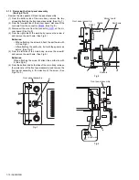
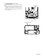
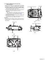
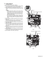
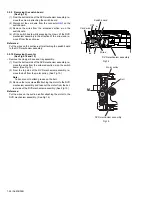
(2) From the forward side of the micom board, disconnect the
card wire from the connector
CN426
. (See Fig.8.)
(3) Disconnect the wire from the connector
CN501
on the mi-
com board. (See Fig.8.)
(4) From the right side of the main body, remove the screw
J
and remove the earth wire. (See Fig.8.)
Reference:
• When attaching the screw
J
, attach the earth wire with
it. (See Fig.8.)
• After attaching the earth wire, fix it with the spacers as
before. (See Fig.8.)
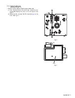
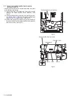
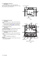
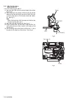
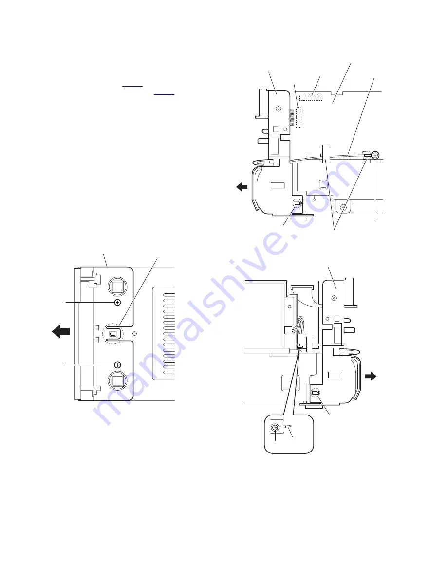
(5) From the left side of the main body, remove the screw
K
and remove the earth wire. (See Fig.9.)
Reference:
When attaching the screw
K
, attach the earth wire with
it. (See Fig.9.)
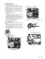
(6) From the bottom and both sides of the main body, release
the joints (
d
,
e
) of the front panel assembly and remove the
front panel assembly in the direction of the arrow. (See
Figs.7 to 9.)
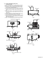
Fig.7
Fig.8
Fig.9
Front panel assembly
d
H
H
Front panel assembly
CN426
CN501
e
Micom board
Earth wire
J
Spacers
Front panel assembly
e
K
Earth wire