background image

For Customer Use:

Enter below the Model No. and Serial 
No. which are located either on the rear, 
bottom or side of the cabinet. Retain this 
information for future reference.

Model No.

Serial No.

LVT0901-001A

[J]

INSTRUCTIONS

MX-G500

 — 

Consists of CA-MXG500 and SP-MXG500.

COMPACT COMPONENT SYSTEM

SP-MXG500

SP-MXG500

CA-MXG500

DISC  CHANGE

C O M P U   P L A Y   C O N T R O L

STANDBY/ON

STANDBY

CD-R/RW PLAYBACK

CLOCK
/TIMER

DISPLAY

PHONES

REPEAT

REC START

/STOP

CD REC

 START

DUBBING

PROGRAM

RANDOM

TAPE B

TAPE A

AUX

TAPE

CD

FM
  /AM

SUBWOOFER

LEVEL

SOUND

MODE

MX-G500

EXTENDED SUPER BASS

CD

3

FULL - LOGIC CONTROL

CD SYNCHRO RECORDING

CD 1

CD 2

CD 3

DISC  CHANGE

C O M P U   P L A Y   C O N T R O L

STANDBY/ON

STANDBY

CD-R/RW PLAYBACK

TUNING

CLOCK
/TIMER

DISPLAY

PHONES

REPEAT

REC START

/STOP

CD REC

 START

DUBBING

PROGRAM

RANDOM

TAPE B

TAPE A

AUX

TAPE

CD

FM
  /AM

SUBWOOFER

LEVEL

SOUND

MODE

MX-GT700

EXTENDED SUPER BASS

CD

3

FULL - LOGIC CONTROL

CD SYNCHRO RECORDING

CD 1

CD 2

CD 3

SP-MXGT700

SP-MXGT700

CA-MXGT700

MX-GT700

 — 

Consists of CA-MXGT700 and SP-MXGT700.

DISC

SKIP

VOLUME

VOLUME

+

RM–SMXG500A REMOTE CONTROL

STANDBY/ON

1

2

3

4

5

6

7

8

9

10

+10

SLEEP

SOUND

MODE

TAPE A/B

FADE 

MUTING

FM/AM

AUX

CD 

TAPE 

SUBWOOFER

LEVEL

FM MODE

DISC

SKIP

VOLUME

VOLUME

+

RM–SMXG500A REMOTE CONTROL

STANDBY/ON

1

2

3

4

5

6

7

8

9

10

+10

SLEEP

SOUND

MODE

TAPE A/B

FADE 

MUTING

FM/AM

AUX

CD 

TAPE 

SUBWOOFER

LEVEL

FM MODE

GT700&G500COVER[J]_f

02.1.16, 9:03 PM

1

Summary of Contents for CA-MXG500

Page 1: ...HRO RECORDING CD 1 CD 2 CD 3 DISC CHANGE C O M P U P L A Y C O N T R O L STANDBY ON STANDBY CD R RW PLAYBACK TUNING CLOCK TIMER DISPLAY PHONES REPEAT REC START STOP CD REC START DUBBING PROGRAM RANDOM TAPE B TAPE A AUX TAPE CD FM AM SUBWOOFER LEVEL SOUND MODE MX GT700 EXTENDED SUPER BASS CD 3 FULL LOGIC CONTROL CD SYNCHRO RECORDING CD 1 CD 2 CD 3 SP MXGT700 SP MXGT700 CA MXGT700 MX GT700 Consists ...

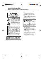
Page 2: ...PARTS INSIDE REFER SERVICING TO QUALIFIED SERVICE PERSONNEL RISK OF ELECTRIC SHOCK DO NOT OPEN The lightning flash with arrowhead symbol within an equilateral triangle is intended to alert the user to the presence of uninsulated dangerous voltage within the product s enclosure that may be of sufficient magnitude to constitute a risk of electric shock to persons The exclamation point within an equi...

Page 3: ...L APPARATUS DOES NOT EXCEED THE CLASS B LIMITS FOR RADIO NOISE EMISSIONS FROM DIGITAL APPARATUS AS SET OUT INTHE INTERFERENCE CAUSING EQUIPMENT STANDARD ENTITLED DIGITAL APPARATUS ICES 003 OF THE DEPARTMENT OF COMMUNICATIONS CET APPAREIL NUMERIQUE RESPECTE LES LIMITES DE BRUITS RADIOELECTRIQUES APPLICABLES AUX APPAREILS NUMIRIQUES DE CLASSE B PRESCRITES DANS LA NORME SUR LE MATERIEL BROUILLEUR APP...

Page 4: ...distance between the unit and the TV Keep the speakers away from the TV to avoid interference with TV DO NOT install the unit in a location near heat sources or in a place subject to direct sunlight excessive dust or vibration We would like to thank you for purchasing one of our JVC products Before operating this unit read this manual carefully and thoroughly to obtain the best possible performanc...

Page 5: ...ing in a Station 11 Presetting Stations 11 Tuning in a Preset Station 11 Playing Back CDs 12 Loading CDs 12 Playing Back CDs All Disc and One Disc 12 Basic CD Operations 13 Programming the Playing Order of the Tracks Program Play 14 Playing at Random Random Play 15 Repeating Tracks or CDs Repeat Play 15 Prohibiting Disc Ejection Tray Lock 15 Playing Back Tapes 16 Playing Back a Tape 16 Recording 1...

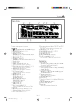
Page 6: ...CK CLOCK TIMER DISPLAY PHONES REPEAT REC START STOP CD REC START DUBBING PROGRAM RANDOM TAPE B TAPE A AUX TAPE CD FM AM SUBWOOFER LEVEL SOUND MODE C D 1 C D 2 C D 3 EXTENDED SUPER BASS 3 FULL LOGIC CONTROL CD SYNCHRO RECORDING C O M P U P L A Y C O N T R O L CD 1 3 2 4 6 8 9 p q w e r t y 5 u j h g f d s a o i 7 EN01 11 MX GT700 G500 J _f 02 1 16 9 03 PM 3 ...

Page 7: ... i Carrousel o 0 Carrousel open close button 12 13 15 Pressing this button also turns on the unit DISC CHANGE button 12 13 Continued a Disc number buttons and lamps CD1 CD2 and CD3 13 15 18 Pressing one of these buttons also turns on the unit s SET button 9 11 14 19 21 d CANCEL DEMO button 8 9 14 20 21 f SOUND MODE control 10 g VOLUME control 10 h SUBWOOFER LEVEL control 10 j Deck B cassette holde...

Page 8: ...C SKIP button 12 y VOLUME button 10 u fast forward forward search button 11 13 16 i 7 stop button 12 18 When using the remote control point it at the remote sensor on the front panel DISC SKIP VOLUME VOLUME RM SMXG500A REMOTE CONTROL STANDBY ON 1 2 3 4 5 6 7 8 9 10 10 SLEEP SOUND MODE TAPE A B FADE MUTING FM AM AUX CD TAPE 2 1 3 SUBWOOFER LEVEL FM MODE 4 6 5 7 8 9 t p q w e r y u i DISC CHANGE C O...

Page 9: ...OT expose batteries to heat or flame DO NOT leave the batteries in the battery compartment when you are not going to use the remote control for an extended period of time Otherwise it will be damaged from battery leakage UM 4 AAA IEC R03 Continued 2 Connecting Antennas FM antenna 1 Attach the FM antenna to the FM 75 Ω coaxial terminal 2 Extend the FM antenna 3 Fasten it up in the position which gi...

Page 10: ... speaker terminal on the rear of the unit 2 Insert the end of the speaker cord into the terminal Match the polarity colors Blue to blue and black to black red to red and black to black If the wire is covered with vinyl remove the vinyl by twisting it as shown in the diagram 3 Release the finger from the clamp IMPORTANT Use only speakers with the same speaker impedance as indicated by the speaker t...

Page 11: ...quipment Connect an optical digital cord not supplied between the optical digital input terminal on the other equipment and the DIGITAL OUT OPTICAL terminal NOW you can plug in the unit and other connected equipment FINALLY Cancelling the Display Demonstration When connecting the AC power cord into a wall outlet the unit automatically starts display demonstration On the unit ONLY To cancel the dis...

Page 12: ...digits start flashing again ON TIME Daily Timer DAILY Canceled ON TIME Recording Timer CLOCK REC 3 Press 4 or to adjust the minute then press SET To check the clock time Press DISPLAY while playing any source Each time you press the button the source indication and the clock time alternate on the display To adjust the clock again If you have adjusted the clock before you need to press CLOCK TIMER ...

Page 13: ...l press VOLUME to increase the volume or press VOLUME to decrease it For private listening Connect a pair of headphones to the PHONES jack No sound comes out of the speakers Be sure to turn down the volume before connecting or putting on headphones DO NOT turn off on standby the unit with the volume set to an extremely high level otherwise a sudden blast of sound can damage your hearing speakers a...

Page 14: ...g for stations On the unit Press and hold TUNING or TUNING for more than 1 second On the remote control Press and hold 4 1 or for more than 1 second The unit starts searching for stations and stops when a station of sufficient signal strength is tuned in If a program is broadcast in stereo the ST stereo indicator lights up To stop during searching press TUNING or TUNING or 4 1 or on the remote con...

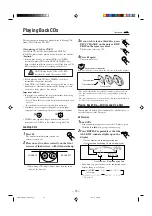
Page 15: ...inalized You can play back your original CD Rs or CD RWs recorded in music CD format ONLY If CD RWs have been recorded in different format erase all the data on CD RWs completely before re recording on the discs DO NOT play back CD Rs or CD RWs recorded the sound files such as MP3 Before playing back CD Rs or CD RWs read their instructions or cautions carefully Some CD Rs or CD RWs may not be play...

Page 16: ...Disc play and restore All Disc play when Turning off the power Ejecting the carrousel or Changing the source to play REPEAT PROG C D 1 C D 2 C D 3 REPEAT ALL DISC REPEAT 1 DISC REPEAT 1 1 DISC ALL DISC initial setting Basic CD Operations While playing a CD you can do the following operations To exchange CDs during playback of another Press DISC CHANGE to change the CD and the carrousel comes out I...

Page 17: ...ifferent disc repeat steps 3 and 4 6 Press CD 6 The tracks are played in the order you have programed To stop during play press 7 To exit from Program play mode press PROGRAM again before or after play so that the unit enters All Disc play mode The program you have made is stored in memory until you turn off the unit eject the carrousel or erase the program Program play mode is also canceled when ...

Page 18: ...eat play mode changes as follows and the following indicator lights up on the display REPEAT 1 Repeats one track on one CD REPEAT 1 DISC Repeats all the tracks on one CD REPEAT ALL DISC Repeats all the tracks on all the CDs See page 12 REPEAT 1 DISC is not used for Program play To cancel Repeat play press REPEAT repeatedly until the REPEAT indicator REPEAT 1 REPEAT 1 DISC or REPEAT ALL DISC goes o...

Page 19: ...arts flashing slowly When the tape plays to the end the deck automatically stops The use of the C 120 or thinner tape is not recommended since characteristic deterioration may occur and this tape easily jams in the pinch rollers and the capstans To stop during play press 7 To operate the other deck press TAPE A or TAPE B or TAPE A B on the remote control then TAPE 3 To fast forward the tape press ...

Page 20: ...the SUBWOOFER LEVEL control Thus during recording you can adjust the sound you are actually listening to without affecting the recording level While recording you can hear sound modes through the speakers or headphones However the sound is recorded without these effects see page 10 If recordings you have made have excessive noise or static the unit may be too close to a TV Place the unit away from...

Page 21: ...ing and the CD player starts playing When the recording is done the CD player and deck B stop To stop during CD Synchronized Recording press REC START STOP or 7 To remove the cassette press EJECT 0 for deck B Dubbing Tapes On the unit ONLY 1 Press TAPE 3 then 7 2 Put the source cassette in deck A and a recordable cassette into deck B 3 Press DUBBING Dubbing starts DUBBING appears and the REC recor...

Page 22: ...tually works The unit automatically turns on set the volume level to the preset level and starts playing the specified source when the on time comes the indicator flashes while the timer is operating Then when the off time comes the unit automatically turns off stands by Daily Timer works every day unless you cancel it There is a time limit in doing the following steps If the setting is canceled b...

Page 23: ...ou can make a tape of a radio broadcast automatically You can set the timer whether the unit is on or off How Recording Timer actually works The unit automatically turns on tunes into the specified station sets the volume level to VOL MIN and starts recording when the on time comes the indicator flashes while the timer is operating Then when the off time comes the unit automatically turns off stan...

Page 24: ...the unit is turned on How Sleep Timer actually works The unit automatically turns off after the specified time length passes On the remote control ONLY 1 Press SLEEP The time length until the shut off time appears and the SLEEP indicator starts flashing on the display Each time you press the button the time length changes as follows 2 Wait for about 5 seconds after specifying the time length The S...

Page 25: ...areful not to scratch the surface of the disc when placing it back in its case Avoid exposure to direct sunlight temperature extremes and moisture To clean the disc Wipe the disc with a soft cloth in a straight line from center to edge DO NOT use any solvent such as conventional record cleaner spray thinner or benzine to clean the disc Cleaning the unit Stains on the unit Should be wiped off with ...

Page 26: ... extended and positioned The disc is scratched or dirty The AC power cord is not plugged in Trays are locked The disc is placed upside down Power supply from the AC power cord has been cut off while the tape was running Small tabs on the back of the cassette are removed The built in microprocessor may malfunction due to external electrical interference The path between the remote control and the r...

Page 27: ...x 129 16 in x 1211 16 in Mass approx 5 0 kg 11 1 lbs each Amplifier section CA MXGT700 Output Power SUBWOOFERS 110 W per channel min RMS driven into 6 Ω at 63 Hz with no more than 10 total harmonic distortion MAIN SPEAKERS 55 W per channel min RMS driven into 4 Ω at 1 kHz with no more than 10 total harmonic distortion Audio input sensitivity Impedance at 1 kHz measured at MAIN SPEAKERS AUX 400 mV ...

Page 28: ...it our website at www JVC com Remember to retain your Bill of Sale for Warranty Service Do not service the television yourself Caution To prevent electrical shock do not open the cabinet There are no user serviceable parts inside Please refer to qualified service personnel for repairs Accessories To purchase accessories for your JVC product please call toll free 1 800 882 2345 or on the web at www...

Page 29: ...rs in shipment due to act of God and cosmetic damage 5 Signal reception problems and failures due to line power surge 6 Video Pick up Tubes CCD Image Sensor Cartridge Stylus Needle are covered for 90 days from the date of purchase 7 Accessories 8 Batteries except that Rechargeable Batteries are covered for 90 days from the date of purchase There are no express warranties except as listed above THE...

Page 30: ...MEMO MEMO 02 1 16 9 04 PM 1 ...

Page 31: ...MEMO MEMO 02 1 16 9 04 PM 2 ...

Page 32: ...VICTOR COMPANY OF JAPAN LIMITED 0102KSMMDWSAM EN J VC GT700 G500COVER J _f 02 1 16 9 03 PM 2 ...

Page 33: ...AYBACK TUNING CLOCK TIMER DISPLAY PHONES REPEAT REC START STOP CD REC START DUBBING PROGRAM RANDOM TAPE B TAPE A AUX TAPE CD FM AM SUBWOOFER LEVEL SOUND MODE MX GT700 EXTENDED SUPER BASS CD 3 FULL LOGIC CONTROL CD SYNCHRO RECORDING CD 1 CD 2 CD 3 SP MXGT700 SP MXGT700 CA MXGT700 MX GT700 DISC SKIP VOLUME VOLUME RM SMXG500A REMOTE CONTROL STANDBY ON 1 2 3 4 5 6 7 8 9 10 10 SLEEP SOUND MODE TAPE A B...

Page 34: ...sted and found to comply with the limits for a Class B digital device pursuant to part 15 of the FCC Rules These limits are designed to provide reasonable protection against harmful interference in a residential installation This equipment generates uses and can radiate radio frequency energy and if not installed and used in accordance with the instructions may cause harmful interference to radio ...

Page 35: ...t damage locate the apparatus as follows 1 Front No obstructions and open spacing 2 Sides Top Back No obstructions should be placed in the areas shown by the dimensions below 3 Bottom Place on the level surface Maintain an adequate air path for ventilation by placing on a stand with a height of 10 cm or more Sideview Côté 1 cm 7 16 in 1 cm 7 16 in 15 cm 5 15 16 in 15 cm 5 15 16 in 15 cm 5 15 16 in...

Page 36: ...t distance between the unit and the TV Keep the speakers away from the TV to avoid interference with TV DO NOT install the unit in a location near heat sources or in a place subject to direct sunlight excessive dust or vibration We would like to thank you for purchasing one of our JVC products Before operating this unit read this manual carefully and thoroughly to obtain the best possible performa...

Page 37: ...Tuning in a Station 11 Presetting Stations 11 Tuning in a Preset Station 11 Playing Back CDs 12 Loading CDs 12 Playing Back CDs All Disc and One Disc 12 Basic CD Operations 13 Programing the Playing Order of the Tracks Program Play 14 Playing at Random Random Play 15 Repeating Tracks or CDs Repeat Play 15 Prohibiting Disc Ejection Tray Lock 15 Playing Back Tapes 16 Playing Back a Tape 16 Recording...

Page 38: ...BACK CLOCK TIMER DISPLAY PHONES REPEAT REC START STOP CD REC START DUBBING PROGRAM RANDOM TAPE B TAPE A AUX TAPE CD FM AM SUBWOOFER LEVEL SOUND MODE EXTENDED SUPER BASS 3 FULL LOGIC CONTROL CD SYNCHRO RECORDING C O M P U P L A Y C O N T R O L CD 1 3 2 4 6 8 9 p q w e r t y 5 u j h g f d s a o i 7 C D 3 C D 1 C D 2 EN01 11 MX GT700 G500 C f pm6 02 2 19 9 33 AM 3 ...

Page 39: ...lder i Carrousel o 0 Carrousel open close button 12 15 Pressing this button also turns on the unit DISC CHANGE button 12 13 Continued a Disc number buttons and lamps CD1 CD2 and CD3 13 15 18 Pressing one of these buttons also turns on the unit s SET button 9 11 14 19 21 d CANCEL DEMO button 8 9 14 20 21 f SOUND MODE control 10 g VOLUME control 10 h SUBWOOFER LEVEL control 10 j Deck B cassette hold...

Page 40: ...SC SKIP button 12 13 y VOLUME button 10 u fast forward forward search button 11 13 16 i 7 stop button 12 18 When using the remote control point it at the remote sensor on the front panel DISC SKIP VOLUME VOLUME RM SMXG500A REMOTE CONTROL STANDBY ON 1 2 3 4 5 6 7 8 9 10 10 SLEEP SOUND MODE TAPE A B FADE MUTING FM AM AUX CD TAPE 2 1 3 SUBWOOFER LEVEL FM MODE 4 6 5 7 8 9 t p q w e r y u i DISC CHANGE...

Page 41: ...r dealer immediately Putting the Batteries into the Remote Control Insert the batteries UM 4 AAA IEC R03 into the remote control by matching the polarity and on the batteries with the and markings on the battery compartment When the remote control can no longer operate the unit replace both batteries at the same time DO NOT use an old battery together with a new one DO NOT use different types of b...

Page 42: ...r of the unit 2 Insert the end of the speaker cord into the terminal Match the polarity colors Blue to blue and black to black red to red and black to black If the wire is covered with vinyl remove the vinyl by twisting it as shown in the diagram 3 Release the finger from the clamp IMPORTANT Use only speakers with the same speaker impedance as indicated by the speaker terminals on the rear of the ...

Page 43: ...TICAL To audio output AUX IN Audio video equipment CANCEL DEMO CANCEL DEMO To connect audio equipment with an optical digital input terminal You can record CD sound onto the connected digital equipment Connect an optical digital cord not supplied between the optical digital input terminal on the other equipment and the DIGITAL OUT OPTICAL terminal NOW you can plug in the unit and other connected e...

Page 44: ...r digits start flashing again ON TIME Daily Timer DAILY Canceled ON TIME Recording Timer CLOCK REC 3 Press 4 or to adjust the minute then press SET To check the clock time Press DISPLAY while playing any source Each time you press the button the source indication and the clock time alternate on the display To adjust the clock again If you have adjusted the clock before you need to press CLOCK TIME...

Page 45: ...rol press VOLUME to increase the volume or press VOLUME to decrease it For private listening Connect a pair of headphones to the PHONES jack No sound comes out of the speakers Be sure to turn down the volume before connecting or putting on headphones DO NOT turn off on standby the unit with the volume set to an extremely high level otherwise a sudden blast of sound can damage your hearing speakers...

Page 46: ... stations On the unit Press and hold TUNING or TUNING for more than 1 second On the remote control Press and hold 4 1 or for more than 1 second The unit starts searching for stations and stops when a station of sufficient signal strength is tuned in If a program is broadcast in stereo the ST stereo indicator lights up To stop during searching press TUNING or TUNING or 4 1 or on the remote control ...

Page 47: ...alized You can play back your original CD Rs or CD RWs recorded in music CD format ONLY If CD RWs have been recorded in different format erase all the data on CD RWs completely before re recording on the discs DO NOT play back CD Rs or CD RWs recorded the sound files such as MP3 Before playing back CD Rs or CD RWs read their instructions or cautions carefully Some CD Rs or CD RWs may not be played...

Page 48: ...Disc play and restore All Disc play when Turning off the power Ejecting the carrousel or Changing the source to play REPEAT PROG C D 1 C D 2 C D 3 REPEAT ALL DISC REPEAT 1 DISC REPEAT 1 1 DISC ALL DISC initial setting Basic CD Operations While playing a CD you can do the following operations To exchange CDs during playback of another Press DISC CHANGE to change the CD and the carrousel comes out I...

Page 49: ...a different disc repeat steps 3 and 4 6 Press CD 6 The tracks are played in the order you have programed To stop during play press 7 To exit from Program play mode press PROGRAM again before or after play so that the unit enters All Disc play mode The program you have made is stored in memory until you turn off the unit eject the carrousel or erase the program Program play mode is also canceled wh...

Page 50: ...playing Each time you press the button Repeat play mode changes as follows and the following indicator lights up on the display REPEAT 1 Repeats one track on one CD REPEAT 1 DISC Repeats all the tracks on one CD REPEAT ALL DISC Repeats all the tracks on all the CDs or all the tracks on the program See pages 12 and 13 REPEAT 1 DISC is not used for Program play To cancel Repeat play press REPEAT rep...

Page 51: ...starts flashing slowly When the tape plays to the end the deck automatically stops The use of the C 120 or thinner tape is not recommended since characteristic deterioration may occur and this tape easily jams in the pinch rollers and the capstans To stop during play press 7 To operate the other deck press TAPE A or TAPE B or TAPE A B on the remote control then TAPE 3 To fast forward the tape pres...

Page 52: ... LEVEL and the SOUND MODE controls Thus during recording you can adjust the sound you are actually listening to without affecting the recording level While recording you can hear sound modes through the speakers or headphones However the sound is recorded without these effects see page 10 If recordings you have made have excessive noise or static the unit may be too close to a TV Place the unit aw...

Page 53: ...ording and the CD player starts playing When the recording is done the CD player and deck B stop To stop during CD Synchronized Recording press REC START STOP or 7 To remove the cassette press EJECT 0 for deck B Dubbing Tapes On the unit ONLY 1 Press TAPE 3 then 7 2 Put the source cassette in deck A and a recordable cassette into deck B 3 Press DUBBING Dubbing starts DUBBING appears and the REC re...

Page 54: ... actually works The unit automatically turns on set the volume level to the preset level and starts playing the specified source when the on time comes the indicator flashes while the timer is operating Then when the off time comes the unit automatically turns off stands by Daily Timer works every day unless you cancel it There is a time limit in doing the following steps If the setting is cancele...

Page 55: ...imer you can make a tape of a radio broadcast automatically You can set the timer whether the unit is on or off How Recording Timer actually works The unit automatically turns on tunes into the specified station sets the volume level to VOL MIN and starts recording when the on time comes the indicator flashes while the timer is operating Then when the off time comes the unit automatically turns of...

Page 56: ...en the unit is turned on How Sleep Timer actually works The unit automatically turns off after the specified time length passes On the remote control ONLY 1 Press SLEEP The time length until the shut off time appears and the SLEEP indicator starts flashing on the display Each time you press the button the time length changes as follows 2 Wait for about 5 seconds after specifying the time length Th...

Page 57: ...e careful not to scratch the surface of the disc when placing it back in its case Avoid exposure to direct sunlight temperature extremes and moisture To clean the disc Wipe the disc with a soft cloth in a straight line from center to edge DO NOT use any solvent such as conventional record cleaner spray thinner or benzine to clean the disc Cleaning the unit Stains on the unit Should be wiped off wi...

Page 58: ...o operate the unit from the remote control If you are having a problem with your unit check this list for a possible solution before calling for service If you cannot solve the problem from the hints given here or the unit has been physically damaged call a qualified person such as your dealer for service Troubleshooting Cause Other buttons are pressed to cancel the display demonstration Connectio...

Page 59: ...in x 129 16 in x 1211 16 in Mass approx 5 0 kg 11 1 lbs each Amplifier section CA MXGT700 Output Power SUBWOOFERS 110 W per channel min RMS driven into 6 Ω at 63 Hz with no more than 10 total harmonic distortion MAIN SPEAKERS 55 W per channel min RMS driven into 4 Ω at 1 kHz with no more than 10 total harmonic distortion Audio input sensitivity Impedance at 1 kHz measured at MAIN SPEAKERS AUX 400 ...

Page 60: ...VICTOR COMPANY OF JAPAN LIMITED 0202KSMMDWSAM EN FR J VC GT700 G500COVER C f pm6 02 2 19 9 32 AM 2 ...

Reviews: