(No.MB306)1-25
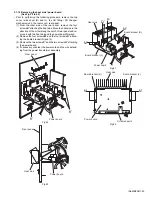
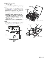
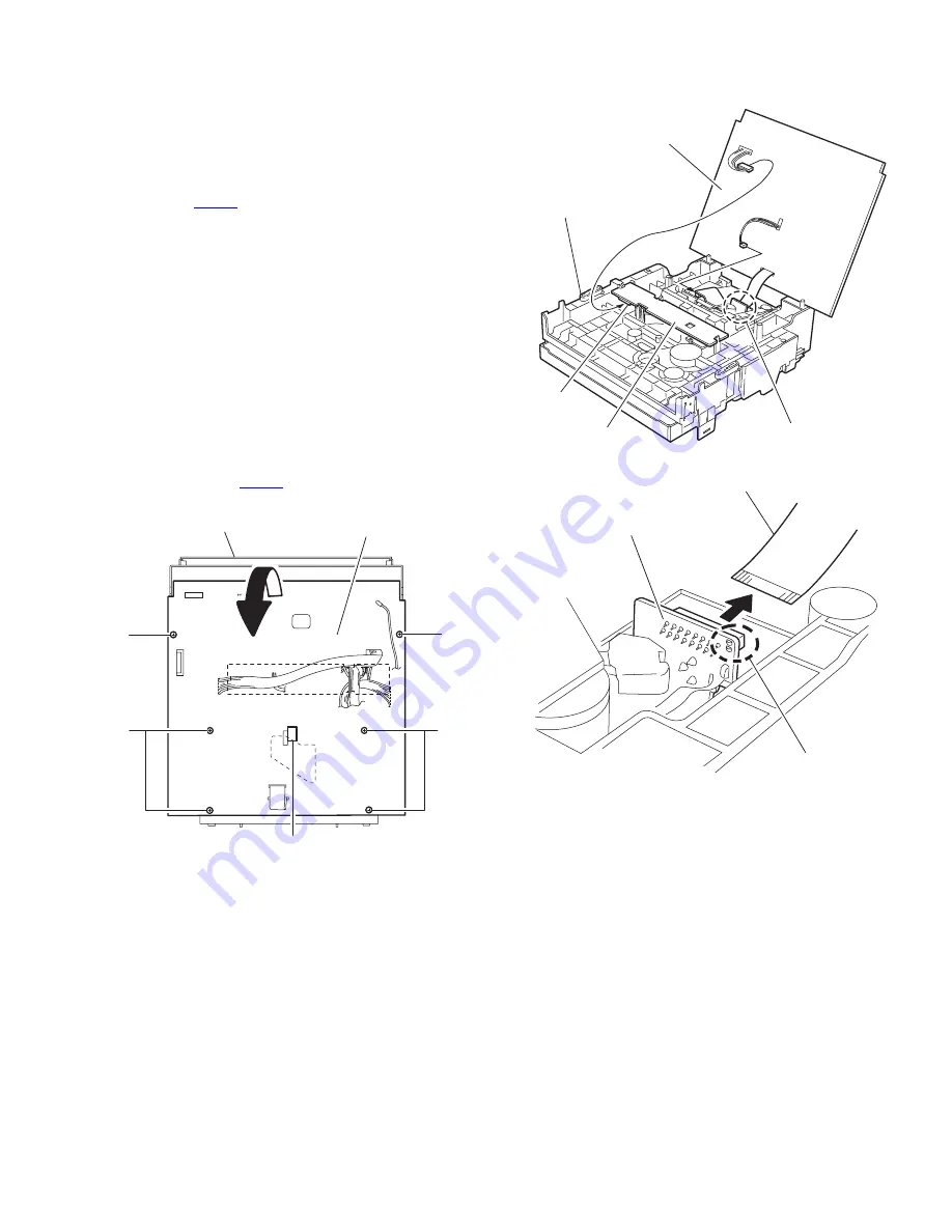
3.1.16 Removing the main board
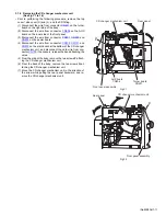
(See Fig.44 to 46)
• Prior to performing the following procedure, remove the top
cover / side cover (R) and (L), the CD fitting / CD changer
mechanism unit.
Caution:
Before disconnecting the card wire from the CD pickup board
and connector
CN401
on the main board, make sure to solder
the short-circuit point on the CD pickup board. If you do not fol-
low this instruction, the pick up may be damaged.
(1) From the bottom of the CD changer mechanism unit, re-
move the two screws
T’
and the four screws
U’
attaching
the main board.
(2) Disconnect the wire from connector on the main board.
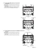
(3) Move the main board in the direction of the arrow as show
in Fig.45, disconnect the wire from connector on the motor
board in the inner part of the main board.
(4) Move the main board turning in the direction of the arrow
ash shown in Fig.45.
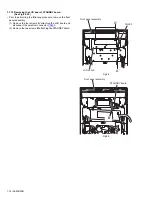
(5) Solder the short-circuit point on the CD pickup board and
disconnect the wire from the CD pickup board.
Caution:
When reattaching the main board, make sure to connect the
card wire to connector
CN401
on the main board and to the CD
pickup board before unsoldering the short-circuit point.
Fig.44
Fig.45
Fig.46
Connector
Main board
CD changer mechanism unit
T'
T'
U'
U'
Main board
Motor board
CW3
Short-circuit point
CD changer
mechanism unit
CD pickup board
Short-circuit point
Card wire
Summary of Contents for CA-MXKB22
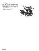
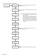
Page 16: ...1 16 No MB306 Fig 23 Fig 24 f Front panel assembly N N Front panel assembly ...
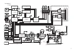
Page 42: ...2 6 TC9462F U401 TO PICK UP TO CD DECK CD section MX KB22 TO MCU ...
Page 43: ...2 7 CD section MX KB1 TC9462F U401 TOMCU TO MCU ...
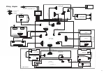
Page 52: ...2 16 Main board forward side reverse side Printed circuit boards ...
Page 53: ...2 17 Display board forward side reverse side Power board forward side reverse side ...
Page 55: ...2 19 Speaker jack board Headphone board forward side reverse side ...
Page 71: ...3 15 MEMO ...

