1-11
NX-HD10
Prior to performing the following procedure, remove
the top cover, the HDD board assembly, the rear
cover, the system control board and the main
amplifier board.
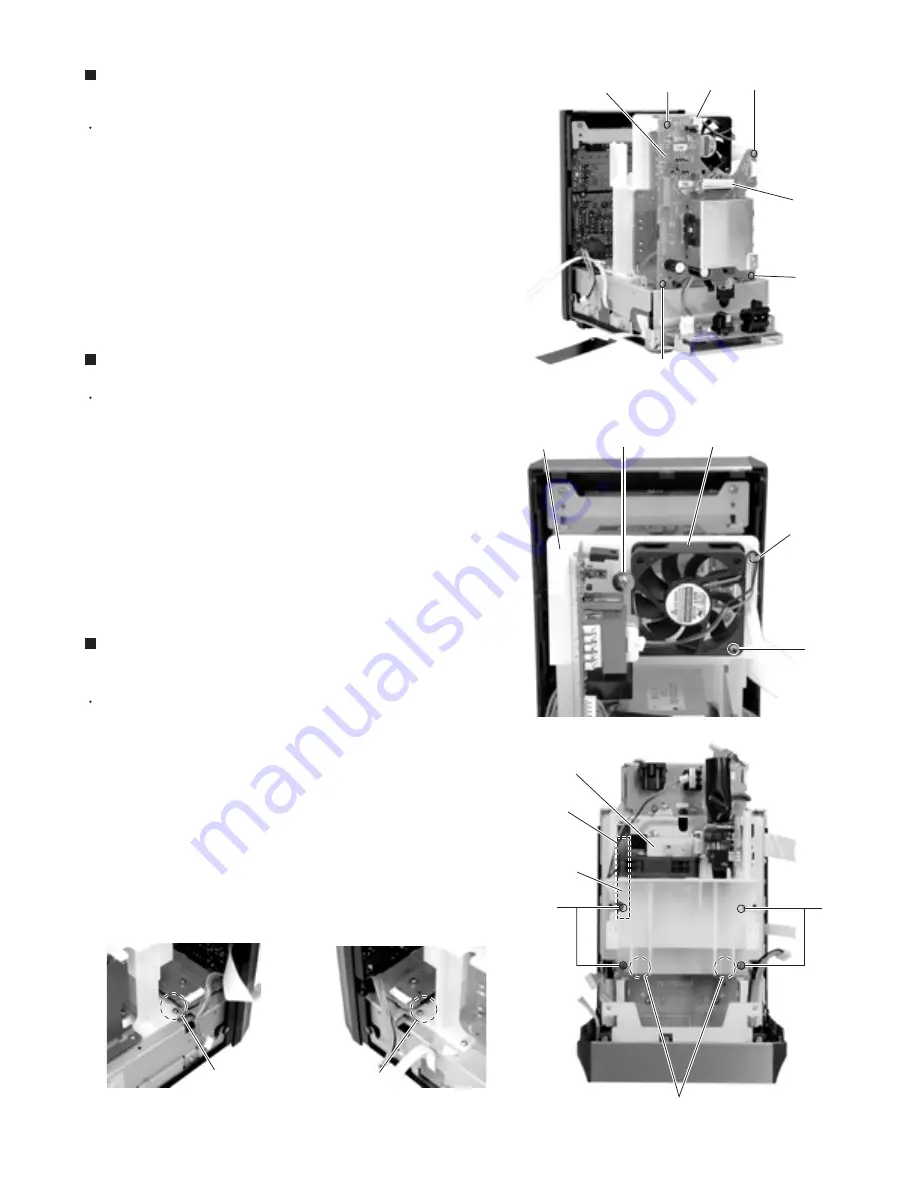
Disconnect the wire from connector CN903 and
CN955 on the back of the body.
Remove the four screws
P
attaching the regulator
board.
1.
2.
Removing the Regulator board
(See Fig.20)
Prior to performing the following procedure, remove
the top cover, the HDD board assembly, the rear
cover, the system control board, the main amplifier
board and the regulator board.
Remove the band setting the fan assembly wire on
the back of the body.
Loosen the screw
Q
and remove the screw
R
attaching the fan assembly.
1.
2.
Removing the Fan assembly (See Fig.21)
Prior to performing the following procedure, remove
the top cover, the HDD board assembly, the rear
cover, the system control board, the main amplifier
board and the regulator board.
Remove the four screws
S
attaching the fan
assembly attaching bracket and the silicon steel
plate. Release the two joints
d
backward and
remove the fan assembly attaching bracket (The fan
assembly will comes off at the same time).
1.
Removing the Power transformer
assembly (See Fig.21~23)
CN903
CN995
P
P
Q
R
P
P
Regulator board
Fan assembly
Fan assembly
attaching bracket
Band
S
S
Power transformer
Fan assembly
attaching bracket
Silicon steel plate
Joint d
Joint d
Joint d
Fig.20
Fig.21
Fig.21-1
Fig.21-3
Fig.21-2
Summary of Contents for CA-NXHD10
Page 62: ...3 2 NX HD10 M E M O ...


