1-13
NX-HD10
Prior to performing the following procedure, remove
the top cover, the HDD board assembly, the front
panel assembly, the rear cover, the system control
board, the main amplifier board, the regulator board,
the fan assembly and the power transformer
assembly.
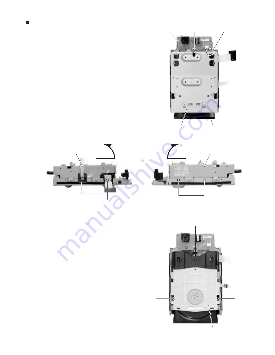
Remove the five screws
V
attaching the CD
mechanism cover.
Lift the front side of the CD mechanism cover to
disengage the joint
e
on the rear side of the CD
mechanism cover.
Remove the three screws
W
.
1.
2.
3.
Removing the CD mechanism assembly
(See Fig.25~28)
CD mechanism assembly
CD mechanism cover
CD mechanism cover
CD mechanism cover
CD mechanism assembly
Joint e
AC jack board
Fig.25
Fig.27
Fig.26
Fig.28
V
V
V
W
W
W
Summary of Contents for CA-NXHD10
Page 62: ...3 2 NX HD10 M E M O ...


