1-20
NX-HD10
Adjustment method
1. Jigs and test instruments
Laser power meter
Laser power meter sensor (or disk sensor)
2. CD check method
For details of the removal, see the previous
section "Disassembly method".
(Caution)
Remove the four screws retaining the top cover from the rear panel and the two screws retaining it from
the left and right side panels.
Remove the two screws retaining the front cover from the rear side and the two screws retaining it from
the bottom panel.
Remove the eight screws retaining the rear cover.
Remove the four screws retaining the sub chassis from the left and right sides.
1.
2.
3.
4.
3. Adjustment and check items
1) CD section
(1) Indication of the C1 error
(2) Cancel of the C1 error indication
4. Adjustment and check method
1) CD section
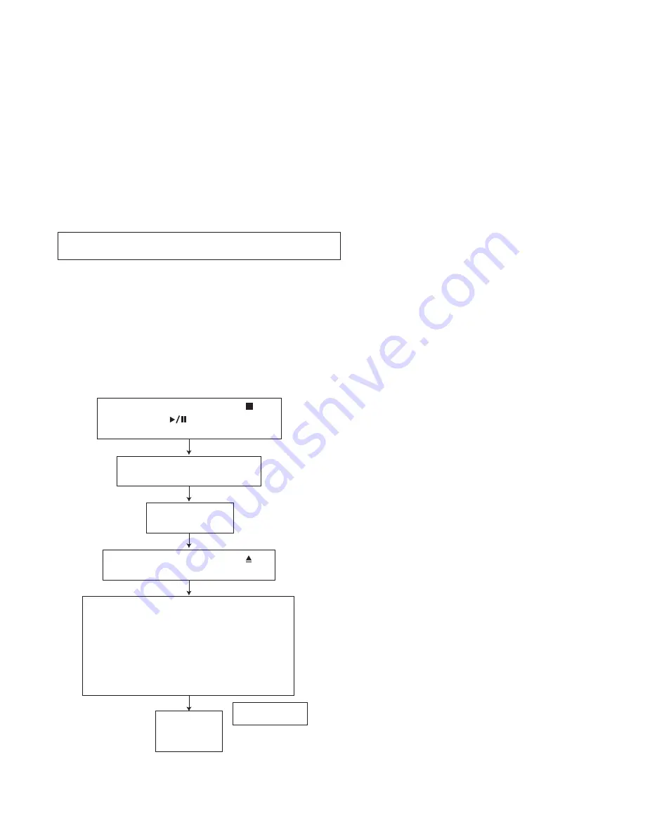
(1) Indication of the C1 error
(2) Cancel of the C1 error indication
To cancel the C1 error indication, cut off the power supply.
FL indication
CD TEST
200 Hz or less
FL indication
∗∗
∗∗
Press the STANDBY/ON key
on the main unit
∗∗∗
Times
Press the CD OPEN/CLOSE key
and insert the test disk.
While pressing both the STOP key
and CD PLAY key on the main
unit,turn on the primary power supply.
Press key 1, 2 or 4 of the remote control
unit to start measurement. The number of
error corrections will be displayed every 10
seconds.
Key 1: Normal-speed playback
Key 2: 2x-speed playback
Key 4: 4x-speed playback
Summary of Contents for CA-NXHD10
Page 62: ...3 2 NX HD10 M E M O ...


