1-39
NX-HD10
RY/BY
buffer
Vcc
Vss
Low Vcc detect
circuit
se
palus
timer
enable
Output
enable
Write circuit
Erase circuit
Input / Output
buffer
Control circuit
(command resistor)
Data latch
Y decoder
X decoder
Address latch
Y gate
4, 194, 304
cell matrix
WE
BYTE
RESET
CE
OE
A
0
~
A
17
A-
1
RY / BY
DQ
0
~
DQ
15
STB
STB
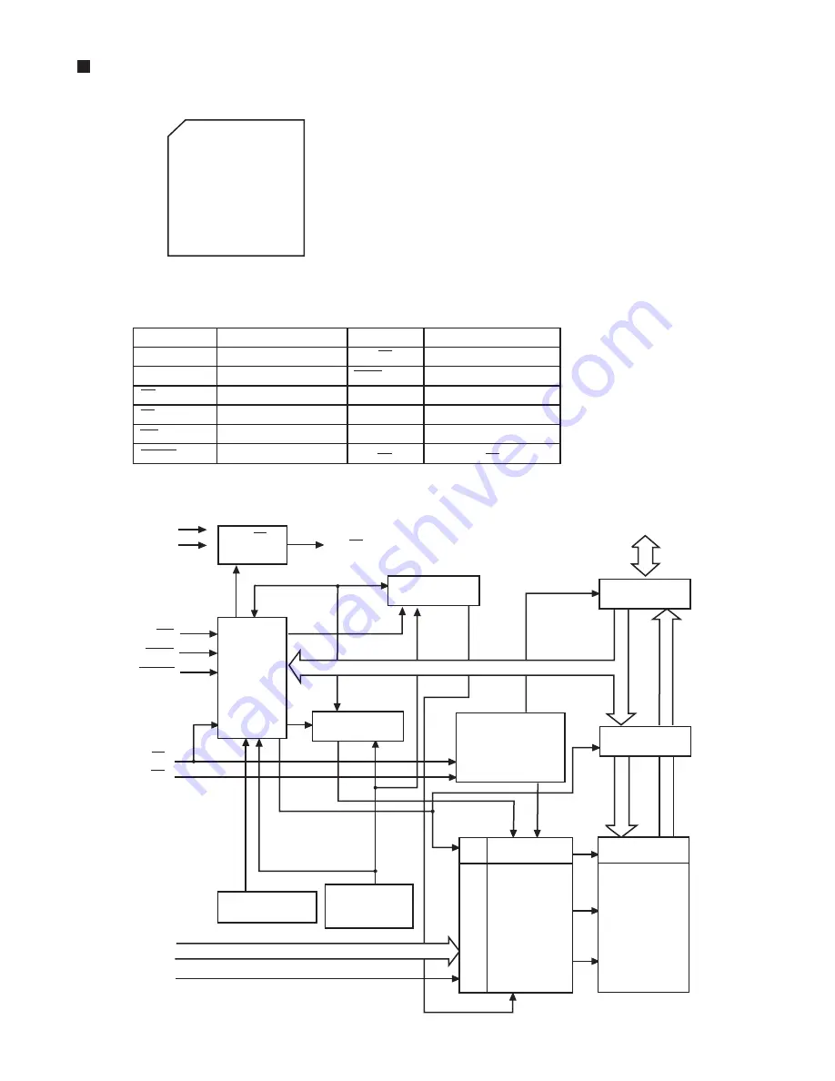
3. Block diagram
Symbol
Function
Symbol
Function
A-
1
, A
0
~A
17
Address input
RY / BY
Ready / Busy output
DQ0
~DQ
15
Data input / Output
BYTE
8bit, 16bit select
CE
Chip enable
Vss
GND
OE
Output enable
Vcc
Power supply
WE
Write enable
N.C.
Not connect
RESET
Hardware reset
2. Pin function
1. Pin layout
MBV400TC70PTB03 (IC950) : 4M-bit flash memory
48
~
25
1
~
24
Summary of Contents for CA-NXHD10
Page 62: ...3 2 NX HD10 M E M O ...


