background image

SERVICE MANUAL

COPYRIGHT © 2003 VICTOR COMPANY OF JAPAN, LIMITED

No.MB049

2003/11

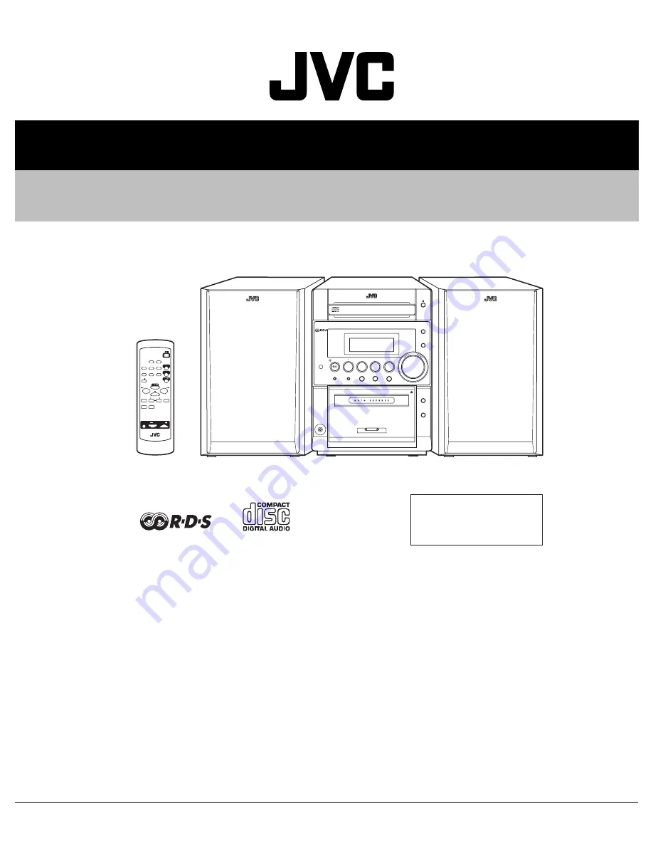
MICRO COMPONENT SYSTEM

MB049

2003

11

UX-P30

TABLE OF CONTENTS

1

Precautions  . . . . . . . . . . . . . . . . . . . . . . . . . . . . . . . . . . . . . . . . . . . . . . . . . . . . . . . . . . . . . . . . . . . . . . . . . .  1-3

2

SPECIFIC SERVICE INSTRUCTIONS . . . . . . . . . . . . . . . . . . . . . . . . . . . . . . . . . . . . . . . . . . . . . . . . . . . . . .  1-7

3

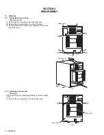
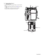
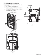
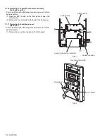
DISASSEMBLY  . . . . . . . . . . . . . . . . . . . . . . . . . . . . . . . . . . . . . . . . . . . . . . . . . . . . . . . . . . . . . . . . . . . . . . .  1-8

4

ADJUSTMENT  . . . . . . . . . . . . . . . . . . . . . . . . . . . . . . . . . . . . . . . . . . . . . . . . . . . . . . . . . . . . . . . . . . . . . . .  1-21

5

TROUBLESHOOTING  . . . . . . . . . . . . . . . . . . . . . . . . . . . . . . . . . . . . . . . . . . . . . . . . . . . . . . . . . . . . . . . . .  1-25

CA-UXP30

SLEEP

STANDBY/ON

AUX

FM/AM

TAPE

CD

DISPLA

Y

REPEA

T

RANDOM

PROG

FM MODE

AUTO

PRESET

SOUND

MODE

CD

CANCEL

MULTI KEY

SET

PTY

/EON

DISPLA

Y

MODE

RM-SUXP3R REMOTE CONTROL

VOLUME

AHB
 

VOLUME

M I C R O   C O M P O N E N T   S Y S T E M     U X - P 3 0

STANDBY

CLOCK

TIMER

CD

/

TAPE

FM/AM

AUX

+

Ð

PHONES

REV.MODE

AHB PRO

SOUND

REC

C D - R / R W   P L A Y B A C K

SP-UXP30

SP-UXP30

Area Suffix

B --------------------------- U.K.
E ------- Continental Europe
EN --------- Northern Europe

Summary of Contents for CA-UXP30

Page 1: ...BLESHOOTING 1 25 CA UXP30 SLEEP ST ANDBY ON AUX FM AM T APE CD DISPLA Y REPEA T RANDOM PROG FM MODE AUTO PRESET SOUND MODE CD CANCEL MUL TI KEY SET PTY EON DISPLA Y MODE RM SUXP3R REMOTE CONTROL VOLUME AHB VOLUME M I C R O C O M P O N E N T S Y S T E M U X P 3 0 STANDBY CLOCK TIMER CD TAPE FM AM AUX Ð PHONES REV MODE AHB PRO SOUND REC C D R R W P L A Y B A C K SP UXP30 SP UXP30 Area Suffix B U K E...

Page 2: ...uning range 522 kHz 1 629 kHz CD player Dynamic range 85 dB Signal to noise ratio 90 dB Wow and flutter Immeasurable Cassette deck Frequency response Normal type I 50 Hz 14 000 Hz Wow and flutter 0 15 WRMS Speaker Speaker units Woofer 8 cm cone 1 Tweeter 2 cm cone 1 Impedance 4 Ω Dimensions approx 160 mm 256 mm 197 mm W H D Mass approx 2 1 kg each General Power requirement AC 230 V 50 Hz Power con...

Page 3: ...one jack control shafts etc to be sure the product is safe to operate without danger of electrical shock Do not use a line isolation transformer during this check Plug the AC line cord directly into the AC outlet Using a Leakage Current Tester measure the leakage current from each exposed metal parts of the cabinet particular ly any exposed metal part having a return path to the chassis to a known...

Page 4: ...same safety characteristics as the recommended replacement parts shown in the Parts List of the Service Manual and may create shock fire or other hazards 4 The leads in the products are routed and dressed with ties clamps tubings barriers and the like to be separated from live parts high temperature parts moving parts and or sharp edges for the prevention of electric shock and fire hazard When ser...

Page 5: ...not possible to adjust the semi fixed resistor that adjusts the laser power Do not turn it 1 8 Attention when traverse unit is decomposed Please refer to Disassembly method in the text for the CD pickup unit Apply solder to the short land sections before the flexible wire is disconnected from the connector CN101 on the CD servo board If the flexible wire is disconnected without applying solder the...

Page 6: ...ation and is equipped with safety switches which prevent emission of radiation when the drawer is open and the safety interlocks have failed or are de feated It is dangerous to defeat the safety switches 5 CAUTION If safety switches malfunction the laser is able to function 6 CAUTION Use of controls adjustments or performance of procedures other than those specified herein may result in hazardous ...

Page 7: ... No MB049 1 7 SECTION 2 SPECIFIC SERVICE INSTRUCTIONS This service manual does not describe SPECIFIC SERVICE INSTRUCTIONS ...

Page 8: ...e two screws B on the side of the body 3 Pull both sides of the metal cover outward and lift the rear part of the cover Fig 1 Fig 2 3 1 2 Removing the rear cover See Fig 3 Prior to performing the following procedure remove the metal cover 1 Remove the two screws C on the back of the body Fig 3 A A A A A Metal cover Metal cover Bx2 C Rear cover Rear panel C ...

Page 9: ...performing the following procedure remove the metal cover 1 Disconnect the card wire from connector CN1 on the tuner board 2 Remove the screw D on the right side of the body 3 Remove the two screws E on the rear panel Fig 4 Fig 5 D CN1 Tuner board E Rear cover Rear panel ...

Page 10: ...the body 4 Move the rear part of the CD mechanism assembly upwards to disengage the two joints a and release from the rear panel Pull the front panel toward the front and move the rear part of the CD mechanism assembly upwards Then pull out the CD mechanism assembly from the front panel backward REFERENCE To remove the CD mechanism assembly efficiently disconnect the card wireconnecting the tuner ...

Page 11: ...assembly 1 Remove the five screws G attaching the rear panel 2 Disconnect the card wire from CN902 on the main board 3 Disengage the lower two joints b on each side of the rear panel using a screwdriver and remove the rear panel backward The tuner board and the fan will be also detached Remove them as needed Fig 9 Fig 10 Joint b Rear panel Rear panel Joint b ...

Page 12: ...m connector CN900 CN901 and CN931 on the main board 2 Disconnect the wire from CN906 and CN907 respectively 3 Remove the two screws H attaching the main board to the chassis on the left side ofthe body and disengage the two joints c 4 Remove the two screws J attaching the heat sink to the main board Fig 11 Fig 12 Fig 13 CN931 CN901 CN900 Main board CN906 CN907 H H Joint c Front panel assembly Main...

Page 13: ...1 Remove the cord stopper upwards on the back of the body 2 Disconnect the power cord from connector J1000 on the board of the power transformer assembly 3 Disconnect the wire from connector FW903 on the main board 4 Remove the four screws K attaching the power transformer assembly Fig 14 Fig 15 J1000 Power cord Cord stopper Power transformer assembly K J1000 Power transformer assembly Main board ...

Page 14: ...0 CN901 and CN931 on the main board Refer to Fig 11 2 Disconnect the wire from connector CN906 and FW903 on the main board Refer to Fig 11 3 Remove the two screws L on each lower side of the body 4 Release the lower joints d on each side of the body using a screwdriver Pull out thefront panel assembly toward the front Fig 16 Fig 17 L Joint d Front panel assembly Main board L Joint d Front panel as...

Page 15: ...e VOLUME knob on the front panel 2 Remove the six screws M attaching the switch board Then open the switch board in the direction of arrow and remove the operation button 3 Remove the ten screws N attaching the Display board and the two screws P of the LCD holder Fig 18 Fig 19 Fig 20 Front panel assembly VOLUME knob M M Switch board N N P N Display board Switch board ...

Page 16: ... to open the cassette door 2 Remove the four screws R on the back of the front panel 3 1 11 Removing the headphone board See Fig 21 Prior to performing the following procedure remove the front panel assembly 1 Remove the screw Q on the back of the front panel Fig 21 Fig 22 R R Display board Cassette mechanism assembly Headphone board R Q Switch board Front panel assembly EJCT button Cassette door ...

Page 17: ...ise as you turn the flywheel R counterclockwise See Fig 2 and 3 3 Disconnect the flexible wire from connector CN31 on the head amplifier mechanism control board 4 Remove the spring from the back of the head 5 Loosen the azimuth screw for reversing attaching the head 6 Remove the head on the front side of the head mount Fig 1 Fig 2 Fig 3 Cassette mechanism assembly Fly wheelR Trigger arm Head mount...

Page 18: ...l pulse board REFERENCE If necessary unsolder the 4 pin wire soldered to the main motor 3 2 3 Removing the main motor See Fig 4 7 1 Remove the two screws B 2 Half raise the motor and remove the capstan belt from the motor pulley ATTENTION Be careful to keep the capstan belt from grease When reas sembling refer to Fig 6 and 7 for attaching the capstan belt Fig 4 Fig 5 Fig 6 Fig 7 Head amplifier mec...

Page 19: ...ard Fig 8 Fig 9 3 2 5 Removing the reel pulse board and solenoid See Fig 10 Prior to performing the following procedure remove the head amplifier mechanism control board 1 Remove the screw C 2 Release the tab a b c d and e retaining the reel pulse board 3 Release the tab f and g attaching the solenoid on the reel pulse board 4 The reel pulse board and the solenoid come off Fig 10 Fly wheel R Fly w...

Page 20: ...the left to disengage the gear If the gear can not be disengaged easily push up the boss Q slightly and raise the rear side of the head mounts slightly to return the direction lever to the reversing side 2 Tighten the azimuth screw for reversing 3 Reattach the spring from the back of the Play Record Clear head 4 Connect the flexible wire to connector CN31 on the head amplifier mechanism control bo...

Page 21: ...ic voltmeter for two channels therefore the earth should be connect ed particularly carefully 7 In the case of BTL connection amp the minus terminal of speaker is not for earthing Therefore be sure not to connect any other earth terminal to this terminal This system is of an BTL system 8 For connecting a dummy resistor when measuring the output use the wire with a greater code size 9 Whenever any ...

Page 22: ...1IC31 8 9 IC32 1 16 16 1 8 9 IC33 L301 Q101 Q201 Q305 Q302 B168 C334 B Q375 E Q376 Q371 B E C201 R101 R102 C104 R105 R106 R107 R108 C221 R110 R111 R112 R121 R201 R202 C204 R205 R206 R207 R208 C111 R210 R211 R212 R221 R301 R303 R304 B167 R335 R315 R314 R313 R310 R122 Q103 R305 B151 R371 R375 R376 R372 R338 R337 R341 R342 R343 R339 R336 R331 VR31 VR37 C210 C110 C102 C101 Q372 C213 C211 R215 D375 R11...

Page 23: ... terminal Speaker out or Headphone out Playback the test tape VT712 3kHz at end of forward side adjust to 2 940 3 90Hz indication of frequency counter by VR37 2 940 3 090Hz VR37 Item Condition Measurement method Ref value Adjustment position Tape speed diviation at FWD REV Test tape VT712 3kHz Output terminal Speaker out or Headphone out Playback the test tape VT712 3kHz at end of forward and reve...

Page 24: ...n start recording the 1kHz and 10kHz of reference fre quency from oscillator 3 Playback the recorded position 1kHz and 10kHz output deviation should 1dB 2dB to readjust by VR31 for Lch and VR32 for Rch Output deviation 1kHz 10kHz 1dB 2dB VR31 Item Condition Measurement method Ref value Adjustment position Recording bias current Forward or Reverse Test tape TYPE ll AC 514 Measurement terminal BIAS ...

Page 25: ...reading finishes Automatic measurement of TE amplitude and automatic tuning of TE balance 500mv div 2ms div Fig 1 Approx 1sec pin 20 of IC601 TE Approx 1 7V VREF Tracking error waveform at TOC reading Power ON Power Key Confirm that the Focus error S cuve ie at the pin23 of IC601 is approx 2Vp p Confirm that the siganl from pin 5 6 of IC801 is a 2V accelerated pulse with approx 700ms Confirm the w...

Page 26: ...al block do not touch the semi fixed resistor If the laser power is lower than the specified value the la ser diode is almost worn out and the laser pickup should be replaced If the semi fixed resistor is adjusted while the pickup is functioning normally the laser pickup may be damaged due to excessive current 5 3 Replacement of laser pickup CD Is the level of RFOUT under 1 1V 0 15Vp p Replace it ...

Page 27: ... No MB049 1 27 ...

Page 28: ... No MB049 AV MULTIMEDIA COMPANY AUDIO VIDEO SYSTEMS CATEGORY 10 1 1chome Ohwatari machi Maebashi city 371 8543 Japan VICTOR COMPANY OF JAPAN LIMITED WPC Printed in Japan ...

Page 29: ...UND MODE CD CANCEL MULTI KEY SET PTY EON DISPLAY MODE RM SUXP3R REMO TE CO NTRO L V O LUM E A H B PR O VOLUME M I C R O C O M P O N E N T S Y S T E M U X P 3 0 STANDBY CLOCK TIMER CD TAPE FM AM AUX Ð PHONES REV MODE AHB PRO SOUND REC C D R R W P L A Y B A C K SP UXP30 SP UXP30 Area Suffix B U K E Continental Europe EN Northern Europe Contents Block diagram 2 1 Standard schematic diagrams 2 2 Print...

Page 30: ...e silk screen printed side parts side of the PWB diagrams the parts that are printed over with black such as the resistor diode and ICP or identified by the mark nearby are critical for safety This regulation does not correspond to J and C version ...

Page 31: ...TERMINAL J1 ANT VT LPF OUT FMOSC OSCOUT MPX FM OUT DI DO CK CE RDDA RDCL 8 4 1 1 27 23 2 16 17 L R OUT AUX IN L R AUX IN L R L R OUT VOLCK VOLDA VOLCE MODE SCL DATE INH LCDCE KEY1 PLAY SAFETY1 SCK SDATE LATCH VOLCE POUT SUBQ SQCK SLK STAT SUBQ SQCK SLK STAT XRST MCLK MDATA MLD XRST MCLK MDATA MLD 45 46 44 49 50 73 72 XT1 2 70 69 X1 2 L R IN TU L R CD L R REC L R PB L R LINE OUT L R PLAY L R IC32 P...

Page 32: ...1145 001 QGA7901C1 2 QQR1145 001 QGA7901C1 2 QQT0284 002 QQR1145 001 QQT0284 002 QQT0284 002 QGA7901C1 2 QQR1145 001 QSW0812 001 QQT0284 003 QUM154 17DGZ4 QUM154 17DGZ4 QUM154 17DGZ4 QUM154 17DGZ4 0 1u 0 1u 0 1u 6A10E2 6A10E2 6A10E2 6A10E2 0 1u 0 1u 0 1u 0 1u 6A10E2 6A10E2 6A10E2 6A10E2 0 1u 0 1u 0 1u 0 1u 6A10E2 6A10E2 6A10E2 6A10E2 0 1u 0 1u 0 1u 0 1u 6A10E2 6A10E2 6A10E2 0 1u 6A10E2 VL A GND A ...

Page 33: ...XL CDL PBL TUL POUT DC regulator Audio output External input Souce selector switch section IC910 R2231 R2125 B2070 D2204 CN907 C2215 J5000 L5034 W5000 C2026 C2126 K5021 L5031 K5020 L5032 L2200 R5000 R5001 C2503 L2201 R3207 R3209 IC901 CN906 R2107 R2007 C2019 C2119 C2117 Q2210 Q2209 R2115 R2015 R2207 R2208 C2214 C2213 D2205 D2206 R2147 R2025 R2047 C2211 D2200 D2201 C2027 Q2213 R2027 R2127 Q2214 C21...

Page 34: ...F1 13 100P 150P 100P 2 2K 0 001 0 001 10K 1K 1K KRC111M T 10K 2 2K 1K 1K MTZJ10C T2 MTZJ10C T2 10K 10K QLD0160 001 1 2K 1 5K 390 390 100P SELU1E54CM P SELU1E54CM P 10K SELU1E54CM P 390 0 01 1SS133 T2 47K QGF1205F1 16 0 001 0 01 2 2K 1K 100K 1K 100P 2 2K 2 2K 2 2K 47K QQR0621 001Z UN2215 X 10K 2 2K 12K QQL231K 4R7Y 15K 2 2K 10K 2 2K 2 2K MTZJ5 1C T2 33K 2SD601A RS X 1K 100K 1SS133 T2 10K MTZJ8 2B T...

Page 35: ... 022 0 022 680K 270K 0 0022 0 1 91 10 100 16 NI 47K MN662748RPMFA 39K 4 7K 4 7 LB1641 470P 12P QAX0413 001Z 12P NI NI NI 0 1 16 0 1 16 1K 1M NI NI NI NI NI NI NI 1K NI 1K NI NI NI NI NI 0 0022 0 0022 4 7K NI 0 NI 220 10 NI NI 2200P NI 150P 150P 150P 150P 680K 560K 4 7K 4 7K 0 047 E406783 001 ESB110 005 E406783 001 100 NI 22K 4 7K NI NI 22K 4 7K 8 2K NI 0 1 16 2SA952 LK T LA6541 X 1K 390P 390P 2 7K...

Page 36: ... 5U2LWA 2 2K QGF1201F3 10 CD4094BC 10 330P HA12237F 4 7 10K 10K 15K 15K KRC107M T 0 01 12K 9 1K 100 27K 2 2K QGF1205F1 09 QGF1205F1 09 QVP0077 103Z 330P QQR1118 001 10 16V VKZ3174 00B 3 3K SG 105F3 9 1K 3 3K 270P 2SB562 C KRC107M T 0 01 22K 47 50V 1 50V 47 50V QAH0101 001 2SK2001 0 0068 27K 11K 470K 4 7K KRA111M T 4 7K 4 7K 4 7K 2SC3576 JVC T 2SC3576 JVC T 2SC3576 JVC T 2SC3576 JVC T 10k 2SK2001 0...

Page 37: ...12P 4 7K 10 50 100 4 7 12P 10K 3 3K 5 6K 10K 0 047 150P 560P 10K LA1838 100 10 0 001 QAX0458 001Z QGF1205F1 13 10 16 39K 10 16 22 16 0 0018 39K 0 0018 10K 0 022 1 50 1K 0 1 0 0022 100 10 0 001 1K 150P 330P 150P 0 01 0 01 0 47 50 1SS133 T2 QQR0793 001 22P 22P 1SS133 T2 1SS133 T2 1SS133 T2 22 16 0 001 1000P QQR0796 002 DTA114YKA X 0 001 0 047 470P QNB0014 001 0 0039 330 220K 330 330 0 01 1 8K 330 10...

Page 38: ...31 R7132 R7133 R7134 R7135 R7136 R7137 R7138 R7139 R7140 R7141 R7142 R7143 R7144 R7145 R7146 R7147 R7148 R7150 R7151 R7152 R7153 R7154 R7155 C2501 C2502 R7201 R7202 R7203 R7206 R7214 R7215 R7217 R7218 R7236 R7238 R7232 R7239 R7240 R7247 R7252 R7253 R7254 R7255 R3200 X7002 IC903 IC904 IC902 J901 Q2204 Q2205 Q2206 Q2207 Q2209 Q2210 Q2212 Q2213 Q2215 Q2216 Q2219 Q2220 Q2222 Q2224 D3222 R3208 CN931 R3...

Page 39: ...R7301 R7302 R7306 R7307 R7308 R7309 R7310 R7313 R7314 R7315 R7316 S7302 S7303 S7306 S7307 S7308 S7309 S7310 S7311 S7315 S7316 C7301 C7302 C7309 C7307 C7341 C7351 C7352 CN932 D7322 D7323 D7331 D7361 D7362 D7363 DI934 FW931 IC933 IC934 JS731 Q7331 R7303 R7304 R7305 R7311 R7312 R7321 R7322 R7323 R7331 R7341 R7342 S7304 S7305 S7312 S7313 S7314 C7305 D7321 Trans board Front board Sub switch board Headp...

Page 40: ...5 R346 R353 R372 R375 R376 VR31 CN32 C204 C104 R109 Q347 R347 W1 W1 PP300 C220 C120 C10 C11 C12 C13 C14 C15 C16 C17 C18 C19 C1 C20 C21 C22 C23 C24 C2 C30 C31 C32 C33 C34 C35 C36 C37 C38 C39 C40 C41 C42 C43 C44 C45 C46 C47 C48 C49 C50 C51 C52 C53 C54 C55 C56 C57 C70 C71 C72 C73 C74 C75 C76 CF1 CF2 CF3 B64 D11 IC1 IC2 J1 L1 L2 L3 L70 Q1 Q2 Q3 Q4 Q5 R10 R11 R12 R13 R14 R15 R16 R17 R18 R19 R20 R21 R22...

Page 41: ... M E M O ...

Page 42: ...VICTOR COMPANY OF JAPAN LIMITED AV MULTIMEDIA COMPANY AUDIO VIDEO SYSTEMS CATEGORY 10 1 1chome Ohwatari machi Maebashi city 371 8543 Japan No MB049SCH Printed in Japan WPC ...

Page 43: ... Block No M1 Speaker assembly and parts list Block No M2 CD loading base assembly and parts list Block No MD Cassette mechanism assembly and parts list Block No MP Electrical parts list Block No 01 06 Packing materials and accessories parts list Block No M3 UX P30 3 2 3 5 3 6 3 8 3 10 3 16 Area suffix B U K E Continental Europe EN Northern Europe MB049 ...

Page 44: ...38 38 35 34 33 37 31 40 70 23 21 20 59 49 51 46 36 39 Main board 11 10 7 6 72 54 50 16 14 13 3 53 1 2 18 15 73 53 4 5 8 8 8 8 47 48 17 9 87 81 86 85 83 84 32 30 12 79 58 8 d e n a F CD servo board e d b k h a g B D G k G C Main board 㨒 31 Block No M M M 1 ...

Page 45: ... 71 70 71 60 63 68 62 67 64 64 61 41 42 44 45 45 45 27 27 28 23 21 20 43 25 26 24 22 52 52 29 11 10 74 8 8 8 8 8 57 56 66 87 82 81 77 78 55 75 88 12 80 58 8 D F E E A B Power suplly board G k 㨒 Tuner board 65 M M M 1 ...

Page 46: ...GV10065 001A CHASSIS BASE 45 GV40312 002A FOOT SPACER x4 P30B P30E 45 GV40184 001A FOOT SPACER x4 P30E N 46 GV30166 001A HEAT SINK A 47 GV40206 001A MICA SHEET A 48 QYSBSF3012Z TAP SCREW 3mm x 12mm x2 49 QYSBSF3016Z TAP SCREW 3mm x 16mm x2 P30B P30E 49 QYSBSFG3016Z SCREW 3mm x 16mm x2 P30E N 50 GV40167 001A H SINK BRACKET 51 GV30168 001A IC BRACKET 52 QYSBST4006Z SCREW 4mm x 6mm x4 53 QYSSST3008Z ...

Page 47: ...s list Speaker assembly Block No M 2 M M 3 1 2 4 Block No M M M 2 Symbol No Part No Part Name Description Local 1 ASW803225 0001 CLOTH FRAME ASS x2 2 FSB810530 0401 WOOFER x2 3 NSP845051 4162 SCREW x8 4 YLB806001 0541 SPEC LABEL x2 ...

Page 48: ...mbly and parts list Grease G 474C EBS0006 009B 4 14 11 7 17 1 13 10 13 12 15 9 8 6 6 5 13 18 3 2 2 16 Block No M M M D Dimension gap for motor pulley 6 9 0 2mm FIG A Apply grease to groove and support convex LOAD JEM 2M FIG A ...

Page 49: ...TCH 5 QYSPSPT2640Z SCREW 2 6mm x 4mm x2 6 E75984 221SS MOTOR PULLEY 7 E75950 002 C D BELT 8 E75985 221SS C D GEAR 1 9 E75986 221SS C D GEAR 2 10 E75987 221SS C D GEAR 3 11 E307162 331SS LEVER 12 E307252 331SS CAM PLATE 13 E65923 003 TAPPING SCREW x3 14 VYH7787 001 SPRING 15 QYSBSF3008Z SCREW 3mm x 8mm 16 E307179 222SM E BASE ASSY 17 E60912 005SS SPEED NUT 18 VMW1329 102 P W BOARD 1 5 ...

Page 50: ...M 30L UD 24 LEN 320M MOBIL 1 1 27 13 3 34 2 8 15 10 14 16 7 12 23 3 2 4 9 6 5 24 29 25 22 17 20 19 18 11 21 31 36 26 33 28 32 33 32 30 1 11 6 5 Switch board The lower side Head amplifier board B 8 7 _ 0 1 0 15 mm A B SLC S302M Block No M M M P 35 35 A C C ...

Page 51: ...14 LV41584 001A BRAKE R 15 LV41585 003A BRAKE L 16 QYSBSF2005Z SCREW 2mm x 5mm 17 VKS5603 00G MAIN PULLEY ASS 18 VKS3785 001MM FR ARM 19 VKW5284 002 SWING SPRING 20 VKS2278 003 TRIGGER ARM 21 VKW5301 001 FR SPRING 22 VKW5266 001 ELEVATOR SPRING 23 WDL214025 WASHER 24 QYSBSF2005Z SCREW 2mm x 5mm 25 VKS3786 00G CLUTCH ASSY 26 VKF3205 00B F WHEEL ASSY R 27 WDL183425 SLIT WASHER 28 VKF3207 00C F WHEEL...

Page 52: ...L1000 QQR1145 001 COIL L5031 QQL231K 470Y COIL 47uH K L5032 QQL231K 470Y COIL 47uH K L5034 QQL231K 470Y COIL 47uH K CN932 QGF1205F1 17 CONNECTOR FFC FPC 1 17 DI934 QLD0160 001 LCD MODULE EP940 E409182 001SM GRAND TERMINAL FW931 QUM025 05Z3Z3 TM FLAT FW943 QUM154 17DGZ4 FLAT WIRE J1000 QGA7901C1 02 CONNECTOR W B 1 2 J5000 QNS0170 001 HEADPHONE JACK JS731 QSW0917 001 R ENCODER K5020 QQR0779 001Z COI...

Page 53: ...04 EEKC1AM 107ZJC E CAPACITOR Symbol No Part No Part Name Description Local C7005 QDYB1CM 103Y C CAPACITOR 0 01uF 16V M C7006 QCSB1HJ 180Y C CAPACITOR 18pF 50V J C7007 QCSB1HJ 180Y C CAPACITOR 18pF 50V J C7008 EETB0JM 228JC E CAPACITOR C7009 QETN1HM 225Z E CAPACITOR 2 2uF 50V M C7010 QETN1HM 475Z E CAPACITOR 4 7uF 50V M C7011 QETN1CM 107Z E CAPACITOR 100uF 16V M C7012 QCFB1HZ 104Y C CAPACITOR 0 1u...

Page 54: ... 102Y C RESISTOR 1kΩ 1 4W J R7143 QRE141J 222Y C RESISTOR 2 2kΩ 1 4W J R7144 QRE141J 222Y C RESISTOR 2 2kΩ 1 4W J R7145 QRE141J 102Y C RESISTOR 1kΩ 1 4W J R7146 QRE141J 222Y C RESISTOR 2 2kΩ 1 4W J R7147 QRE141J 102Y C RESISTOR 1kΩ 1 4W J R7148 QRE141J 222Y C RESISTOR 2 2kΩ 1 4W J R7149 QRE141J 103Y C RESISTOR 10kΩ 1 4W J R7150 QRE141J 222Y C RESISTOR 2 2kΩ 1 4W J R7151 QRE141J 222Y C RESISTOR 2 2...

Page 55: ...R606 NRSA63J 472X MG RESISTOR 4 7kΩ 1 16W J R607 NRSA63J 623X MG RESISTOR 62kΩ 1 16W J R610 NRSA63J 223X MG RESISTOR 22kΩ 1 16W J R611 NRSA63J 223X MG RESISTOR 22kΩ 1 16W J R612 NRSA63J 822X MG RESISTOR 8 2kΩ 1 16W J R613 NRSA63J 472X MG RESISTOR 4 7kΩ 1 16W J R615 NRSA63J 472X MG RESISTOR 4 7kΩ 1 16W J R616 NRSA63J 472X MG RESISTOR 4 7kΩ 1 16W J Symbol No Part No Part Name Description Local R617 ...

Page 56: ... K R2 NRSA02J 331X MG RESISTOR 330Ω 1 10W J R3 NRSA02J 224X MG RESISTOR 220kΩ 1 10W J R4 NRSA02J 331X MG RESISTOR 330Ω 1 10W J R5 NRSA02J 560X MG RESISTOR 56Ω 1 10W J R6 NRSA02J 120X MG RESISTOR 12Ω 1 10W J R10 NRSA02J 222X MG RESISTOR 2 2kΩ 1 10W J R13 NRSA02J 103X MG RESISTOR 10kΩ 1 10W J R14 NRSA02J 104X MG RESISTOR 100kΩ 1 10W J R15 NRSA02J 332X MG RESISTOR 3 3kΩ 1 10W J R16 NRSA02J 472X MG RE...

Page 57: ... 100uF 10V M C376 QDYB1CM 103Y C CAPACITOR 0 01uF 16V M R101 QRE141J 512Y C RESISTOR 5 1kΩ 1 4W J R102 QRE141J 512Y C RESISTOR 5 1kΩ 1 4W J R104 QRE141J 222Y C RESISTOR 2 2kΩ 1 4W J R105 QRE141J 104Y C RESISTOR 100kΩ 1 4W J R106 QRE141J 113Y C RESISTOR 11kΩ 1 4W J R107 QRE141J 912Y C RESISTOR 9 1kΩ 1 4W J R108 QRE141J 273Y C RESISTOR 27kΩ 1 4W J R110 QRE141J 103Y C RESISTOR 10kΩ 1 4W J R116 QRE141...

Page 58: ...3 16 Packing materials and accessories parts list P4 P3 P2 P7 P5 A1 A2 A3 A4 A5 A6 A7 A8 P1 P6 Block No M M M 3 P8 P9 P10 P10 ...

Page 59: ...ARD P30B P30E A 4 BT 54013 6 WARRANTY CARD P30E N A 5 VNA3000 204 REGISTER CARD P30B A 6 RM SUXP3R REMOCON A 7 BATTERY x2 A 8 UXP30E SPBOX SPEAKER BOX x2 P 1 QPC02503515P POLY BAG 25cm x 35cm P 2 GV20245 001A CARTON P 3 GV10152 001A CUSHION UPPER P 4 GV10153 001A CUSHION BOTTOM P 5 QPC05006515P POLY BAG 50cm x 65cm P 6 GV40168 008A SHEET P30B P30E P 6 GV40168 005A SHEET P30E N P 7 IVA802300 0015 P...

Reviews: