


1-12 (No.MB049)
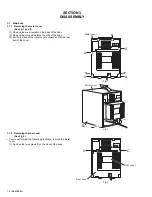
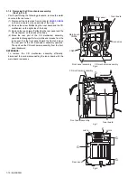
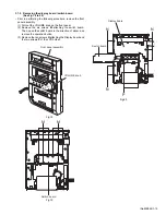
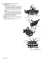
3.1.6
Removing the main board / heat sink
(See Fig.11 to 13)
• Prior to performing the following procedure, remove the metal
cover, the rear cover, the CD mechanism assembly and the
rear panel.
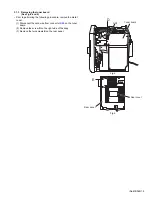
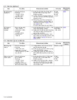
(1) Disconnect the card wire from connector
CN900
,
CN901
and
CN931
on the main board.
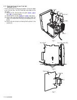
(2) Disconnect the wire from
CN906
and
CN907
respectively.
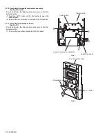
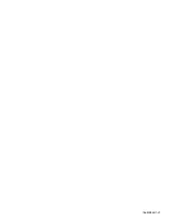
(3) Remove the two screws
H
attaching the main board to the
chassis on the left side ofthe body and disengage the two
joints
c
.
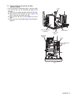
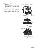
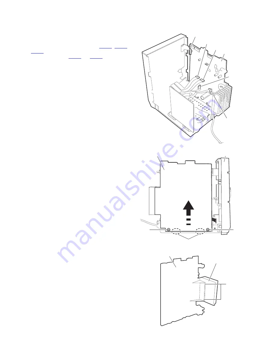
(4) Remove the two screws
J
attaching the heat sink to the
main board.
Fig.11
Fig.12
Fig.13
CN931
CN901
CN900
Main board
CN906
CN907
H
H
Joint c
Front panel assembly
Main board
Heat sink
Main board
J
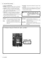
Summary of Contents for CA-UXP30
Page 27: ... No MB049 1 27 ...
Page 41: ... M E M O ...


