


SERVICE MANUAL
CD CHANGER
No.49697
Feb. 2002
COPYRIGHT 2002 VICTOR COMPANY OF JAPAN, LTD.
CH-X460
CH-X460
Contents
Safety precaution
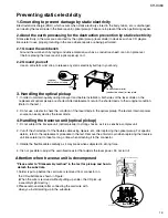
Preventing static electricity
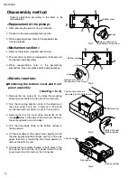
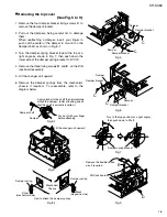
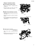
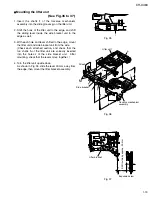
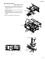
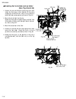
Disassembly method
Forced eject procedures
1-2
1-3
1-4
1-20
Trouble shooting
Flow of functional
operation until TOC read
Description of major ICs
1-21
1-23
1-27
Area Suffix
U ---------------- Other Areas
COM
PACT
DISC
CHA
NGER
12Ð
DISC
CH-X
460


