background image

SERVICE MANUAL

COPYRIGHT © 2003 VICTOR COMPANY OF JAPAN, LTD.

No.49787

2003/01

CH-X550

CD CHANGER

49787

2003

01

CH-X550

TABLE OF CONTENTS

1

Important Safety Precautions  . . . . . . . . . . . . . . . . . . . . . . . . . . . . . . . . . . . . . . . . . . . . . . . . . . . . . . . . . . .  1-2

2

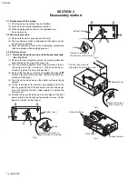
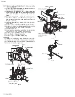
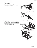
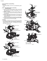
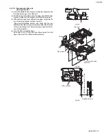
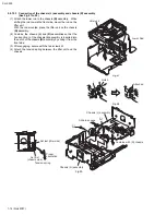
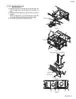
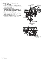
Disassembly method  . . . . . . . . . . . . . . . . . . . . . . . . . . . . . . . . . . . . . . . . . . . . . . . . . . . . . . . . . . . . . . . . . .  1-4

3

Adjustment. . . . . . . . . . . . . . . . . . . . . . . . . . . . . . . . . . . . . . . . . . . . . . . . . . . . . . . . . . . . . . . . . . . . . . . . . .  1-20

4

Description of major ICs. . . . . . . . . . . . . . . . . . . . . . . . . . . . . . . . . . . . . . . . . . . . . . . . . . . . . . . . . . . . . . .  1-27

Area Suffix

E ------- Continental Europe

Summary of Contents for CH-X550

Page 1: ...COMPANY OF JAPAN LTD No 49787 2003 01 CH X550 CD CHANGER 49787 2003 01 CH X550 TABLE OF CONTENTS 1 Important Safety Precautions 1 2 2 Disassembly method 1 4 3 Adjustment 1 20 4 Description of major ICs 1 27 Area Suffix E Continental Europe ...

Page 2: ...utions Burrs formed during molding may be left over on some parts of the chassis Therefore pay attention to such burrs in the case of preforming repair of this system Please use enough caution not to see the beam directly or touch it in case of an adjustment or operation check ...

Page 3: ...ode in the optical pickup The tester s internal power source can easily destroy the laser diode 1 3 Handling the traverse unit optical pickup 1 Do not subject the traverse unit optical pickup to strong shocks as it is a sensitive complex unit 2 Cut off the shorted part of the flexible cable using nippers etc after replacing the optical pickup For specific details refer to the replacement procedure...

Page 4: ...tc to remove it The knob can be re moved only when it is set to this position 3 Remove the four top cover fixing screws B at the triangle marks on the side of the main unit Perform the same op eration on both sides 4 Turn the unit upside down so the bottom surface is facing upward 5 Lift the rear edge of the bottom cover slightly and lift the side by grasping the DIN jack section on the side panel...

Page 5: ...Lift the changer unit upward 6 Remove the damper springs from the mechanism chassis if required To reassemble refer to the diagram below Fig 5 Fig 6 Fig 6 1 Fig 7 Fig 8 Fig 8 1 Fig 9 C C Damper Damper bracket Damper Damper bracket C C Damper Damper bracket Damper bracket Damper Apply alcohol to the shaft then immediately attach the damper After attaching check that the shaft is correctly inserted ...

Page 6: ... screw G 2 Remove the four screws H securing the main board as sembly 3 Disconnect position motor wire connector CN504 from the main board assembly 4 Disconnect sensor board assembly wire connector CN601 from the main board assembly 5 Remove the flexible ribbon wire from CN502 on the traverse mechanism board assembly When reinstalling the board boards refer to the reassembling procedures for prote...

Page 7: ...ront side of the chassis 2 Remove the poly washer c securing the magazine lock arm 3 Turn the magazine lock arm in the direction of the arrow un til the notch is at the d position to remove it from the chas sis Fig 1 Fig 2 2 4 3 Positioning motor assembly See Fig 3 1 Remove the two screws J securing the positioning motor 2 Slightly lift the positioning motor assembly to remove it from the two burr...

Page 8: ...n of the arrow clockwise until the front slider is shifted to the outermost position 2 Remove the E washer securing the front slider to remove the front slider from the chassis Fig 5 2 4 6 Top plate See Fig 6 and 7 1 Remove the nine screws K securing the top plate 2 Disconnect the section e attached to the rear of the unit then lift the top plate slightly 3 Slide the top plate toward the rear of t...

Page 9: ...cated on the back of the lifter unit 2 Remove the lower rod Fig 10 2 4 9 Side bracket and traverse mechanism assembly See Fig 11 1 Remove the two side bracket unit fixing screws M to dis connect the side bracket unit from the lifter unit 2 Remove the three shafts on the traverse mechanism as sembly from the lifter unit CAUTION For reassembling refer to the reassembling procedures Fig 11 Unhook thi...

Page 10: ...to remove the shaft holder retaining the feed slide shaft assembly and the middle gear 7 Move the middle gear 8 Move the pickup assembly upward from the gear section and remove it from the traverse chassis assembly 9 Remove the two screws Q to remove the rack arm 10 Pull out the feed slide shaft assembly 11 Remove the screw R to remove the spring CAUTION To reattach the mechanism board connect the...

Page 11: ...ig 17 2 4 12 Separation of the chassis L assembly and chassis R assembly See Fig 18 1 Remove the two screws U retaining the chassis L and R assemblies 2 Slide the chassis L assembly toward the front and detach it then remove the chassis L upward Fig 18 Tray motor assembly S S Tray motor Tray motor holder T Front side U U Slide and remove upward as shown by the arrow Chassis L assembly Chassis R as...

Page 12: ...t switch is correctly placed 4 To mount the rack arm first move the pickup to the middle position and secure it with the screws Q CAUTION To reattach the mechanism board connect the pickup flexible wire to connector CN501 on the mechanism board before un soldering the short circuit round Subsequently fix the mech anism board using screws Fig 19 Fig 20 Fig 21 Fig 22 Fig 23 Pickup assembly Attached ...

Page 13: ...e mount the lift er unit and side bracket unit from the side Check each attached section and check that the two shafts h of the lifter unit are correctly inserted into the holes i of the side bracket unit After mounting check that the le vers move together 4 Turn the lifter unit upside down As shown in Fig 35 slide the lever 30mm away from the edge then mount the lifter bracket assembly Fig 24 Fig...

Page 14: ...mbine the chassis L and R assemblies so that the hook section j of the chassis L assembly is inserted into the notch of the chassis R assembly by sliding it from the front side 3 After engaging secure with the two screws U 4 Attach the tension spring between the lifter unit and the chassis Fig 27 Fig 28 Fig 29 Lower Rod Lifter unit Notch Attached j Slide to engage Combine with R chassis Set last l...

Page 15: ...f the upper rod to m 2 Check that the five points n o p s and r are correctly po sitioned When mounting section s set it so that section t of the lifter unit is pinched by the bending section of the top plate 3 Secure the top plate with six fixing screws K Fig 30 Fig 31 Fig 32 Fig 33 Upper rod m l K K K Top plate Section t Lifter Unit Point r Expanded view of mounting s n o p s r ...

Page 16: ...th the right hole of the stud as shown in Fig 34 3 Mount the E washer on the shaft 4 Position the unit with the front side facing down then mount the rear slider Check that the u v and w positions are correctly mounted as shown in Fig 35 5 Rotate the third gear in the direction of the arrow counter clockwise until the lifter unit is at the top position Fig 34 Fig 35 Stud E Washer Front slider Chec...

Page 17: ...the shorter spring to the hook of the lift arm Fig 36 2 4 13 7 Mounting the main PC board assembly See Fig 37 1 Rotate the third gear clockwise until section x of the front slider and the third hole from the right are lined up Be sure to set properly If incorrectly set the switches on the board assembly may be damaged 2 After they are correctly positioned mount the main board assembly Fig 37 Senso...

Page 18: ...e the three fixing screws N from the round holes on the chassis R assembly to remove the traverse mecha nism board assembly 11 Remove the pickup shaft holder fixing screw P to remove the pickup assembly CAUTION When replacing the pickup be sure to apply counter measures against static electricity grounding the opera tion table wrist band and soldering iron To remove it first short circuit the grou...

Page 19: ... X550 No 49787 1 19 Fig 42 Fig 43 Fig 44 Pickup Feed slide shaft Rack arm R Q Shaft Holder Middle gear P Pickup Middle gear Chassis Shift approx 30 mm Shift approx 30 mm Lifter unit lever Enlarged diagram ...

Page 20: ...n the tray to the magazine Rotate the third gear clockwise and unchuck the disc Remove the dampers and the top cover to take out the mechanism Remove the item s causing the disc jam through the clearance at the top of the lifter Remove the lifter bracket L and return the tray to the magazine Completed YES YES YES NO NO NO Is the disc set in the playing position Are trays stored in the magazine Che...

Page 21: ...nism assembly E3 Tray motor error Trays cannot be opened or closed when exchanging or ejecting discs Does the tray move when changing or ejecting discs YES 5 NO 6 5 Check that TRAY OUT SW S602 and TRAY IN SW S603 function correctly E4 Pick returning Does the feed pickup unit return to the inner area of the disc when ejecting YES 7 NO 8 9 7 Check the rest switch 8 If the feed gear is rotated check ...

Page 22: ...y E1 03 00 17 Tray in switch time out Tray in switch Low Tray out switch Low Tray in switch faulty or other defect E1 03 00 18 MAG in switch Low to High Magazine removed when tray partly retracted E1 03 00 19 Lifter raise error Wait position time out Position motor inoperative E1 02 00 21 Wait position time out Position not stable in fine adjust mode E1 02 00 22 Wait position time out Other fault ...

Page 23: ... moves to the inner area of the disc When the laser diode correctly emits No disc display Rough Servo Mode CLV Servo Mode ProgramArea CLV Servo Mode Lead In Area Digital 0 RF signal Focus Servo Loop ON TERMINAL Microprocessor commands Microprocessor commands Tracking Servo Loop ON Servo CLV Rough Servo Acceleration Acceleration Acceleration Microprocessor commands Spindle motor FSO TA2109 2 2V 8A ...

Page 24: ...own and stops The position motor does not function The tray motor goes forward and back several times Check the connections to the receiver or the circuits in the vicinity of IC651 Check the linear position sensor VR601 Check the wiring of the CD 9 V power supply position motor Check the TRAY IN and TRAY OUT switches Exchange discs then check whether or not the feed motor moves Set from the STOP t...

Page 25: ...icinity of IC581 pins H K Check the pickup and its connections NO YES YES Does the S search waveform appear at IC581 pins H and I 4V Is the disk rotated Does the RF signal appear at TP1 Is 4V present between IC581 pins 1 and 2 Check the spindle motor and its wiring Is 4V present at IC521 pin x Check the vicinity of IC581 Check IC501 and IC521 YES NO NO NO NO NO YES YES YES Check the circuits in th...

Page 26: ...supply Check IC521 and its peripheral circuits Check IC101 and its peripheral circuits Is 9V present at IC101 pin 8 Is the sound output from both channels L R NO NO NO NO NO YES YES YES YES YES YES Is the audio signal including sampling output components output to IC521 pins and during Is the audio signal output at IC101 pins 1 and 7 during playback Check the muting circuit Normal ...

Page 27: ...1 BA15218F XE IC101 Dual operation amplifier Pin layout Block diagram 1 2 8 Vcc 7 OUT2 6 IN2 5 IN2 OUT1 1 IN1 2 IN1 3 VEE 4 Q19 Q17 Q16 OTHER CH R9 R6 R8 R7 R5 R4 R3 R2 R1 D1 C1 Q18 Q13 Q11 Q8 Q5 Vcc VEE OUTPUT IN IN Q1 Q3 Q4 Q2 C2 Q9 Q6 Q7 Q10 Q12 Q14 Q15 Q114 ...

Page 28: ...ND GND A0 A1 A2 I Slave address setting terminal SCL I Serial clock input terminal SDA I O Slave word address serial data input output WP I Write protect terminal A0 1 A1 2 A2 3 GND 4 8 Vcc 7 WP 6 SCL 5 SDA 1kbit EEPROM 7bit 7bit 8bit Address decoder Slave Word Address register Data register Control circuit High voltage circuit Voltage detection START STOP ACK ...

Page 29: ... I CH6 reverse input 16 SGND Signal ground 17 FWD3 I CH7 forward input 18 REV3 I CH7 reverse input 19 CTL3 I CH7 motor speed control 20 SB I Stand by 21 PS I Power save 22 MUTE I All mute 23 PVCC2 Power supply voltage 24 DO7 O CH7 drive output 25 DO7 O CH7 drive output 26 DO6 O CH6 drive output 27 DO6 O CH6 drive output 28 PGND2 Power ground2 29 DO5 O CH5 drive output 30 DO5 O CH5 drive output 31 ...

Page 30: ...nput Block diagram Note CL includes probe and jig capacitance 1 2 3 4 5 6 7 1C 1A 1Y 2C 2A 2Y GND VCC 4C 4A 4Y 3C 3A 3Y 14 13 12 11 10 9 8 Input Output C A Y L X Z H L H H H L Vcc Vcc Input See Function Table 1A 2A 3A 4A 1C 2C 3C 4C 1Y 2Y 3Y 4Y Output Output Output Output Sample as Load Circuit 1 Sample as Load Circuit 1 Sample as Load Circuit 1 1k 1k S1 CL ...

Page 31: ... IC602 Regulator Pin layout Block diagram Pin function NC 1 GND 2 4 Vcc 3 VOUT Vcc 4 NC 1 3 VOUT 2 GND Pin No Symbol Function 1 NC Non connect 2 GND GND terminal 3 VOUT Reset signal output terminal 4 Vcc Vcc terminal Voltage detect terminal ...

Page 32: ... 15pF 14k 2k 1k 2k 50k x2 x2 240k 60k 80k 80k 20k 20k 180k 40pF 40pF 3k 3k 12k 12k 15k 50 A 10pF 20 A 40k 20k 20k 20k 50k PEAK 15k 10pF 40k 60 A 1 3V BOTTOM PEAK 40k 30k 13 GVSW VRO FEO FEN RFRP RFRPIN RFGO RFGC AGCIN RFO RFN GND 14 15 16 17 18 19 20 21 22 23 24 12 RFDC TEO TEN TEBC SEL LDO MDI TNI TPI FPI FNI Vcc 11 10 9 8 7 6 5 4 3 2 1 ...

Page 33: ... signal peak detection output pin 13 GVSW I AGC FE TE amp gain change pin 14 VRO O Reference voltage VRO output pin VRO 1 2 Vcc when Vcc 3 3V 15 FEO O Focus error signal generation amp output pin 16 FEN I Focus error signal generation amp negative phase input pin 17 RFRP O Signal amp output pin for track count Combining RFRP signal TEO signal with TC9490F FA configures track ing search system 18 R...

Page 34: ...stment circuit RAM Correction circuit 48 47 46 45 44 43 42 41 40 39 38 37 36 35 34 33 1 2 3 4 5 6 7 8 9 10 11 12 13 14 15 16 17 18 19 20 21 22 23 24 25 26 27 28 29 30 31 32 64 63 62 61 60 59 58 57 56 55 54 53 52 51 50 49 BCK LRCK AOUT DOUT IPF V DD3 V SS3 SBOK CLCK DATA SFSY SBSY HSO UHSO PV DD3 PDO VXDD3 XO XI XV SS3 TEIN V DD3 V SS3 DMO FMO AV DD3 SEL TEBC RFGC V REF TRO FOO DVSS3 RO DVDD3 DVR L...

Page 35: ...code sync is detected 13 HSO O Playback speed mode flag output pins 14 UHSO O 15 PVDD3 PLL only 3 3V power supply voltage pin 16 PDO O EFM and PLCK phase difference signal output pin 17 TMAX O TMAX detection result output pin 18 LPFN I Inverted input pin for PLL LPF amp 19 LPFO O Output oin for PLL LPF amp 20 PVREF PLL only VREF pin 21 VCOF O VCO filter pin 22 AVSS3 Analog GND pin 23 SLCO O DAC ou...

Page 36: ...I System clock oscilatoe input pin 47 XO O System clock oscillator output pin 48 XVDD3 System clock oscillator 3 3V power supply voltage pin 49 DVSS3 DA converter GND pin 50 RO O R channel data forward output pin 51 DVDD3 DA converter 3 3V power supply pin 52 DVR Reference voltage pin 53 LO O L channel data forward output pin 54 DVSS3 DA converter GND pin 55 ZDET O 1 bit DA converter zero data det...

Page 37: ...1 open drain 38 BUS2 I O CD LSI data 2 open drain 39 BUS3 O CD LSI data 3 open drain 40 NC Unused output port 41 CD RW O CD RW Detect signal output 42 NC Unused output port 43 NC Unused output port 44 MAG IN Magazine switch Lo magazine inserted 45 TRAY OUT O Tray extend switch Lo extension complete 46 TRAY IN O Tray retract switch Lo retraction complete 47 REST I Resr switch 48 DISC SEL O Disc sel...

Page 38: ... No 49787 AV MULTIMEDIA COMPANY 10 1 1chome Ohwatari machi Maebashi city 371 8543 Japan VICTOR COMPANY OF JAPAN LIMITED 200301WPC Printed in Japan CH X550 ...

Reviews: