


.
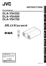
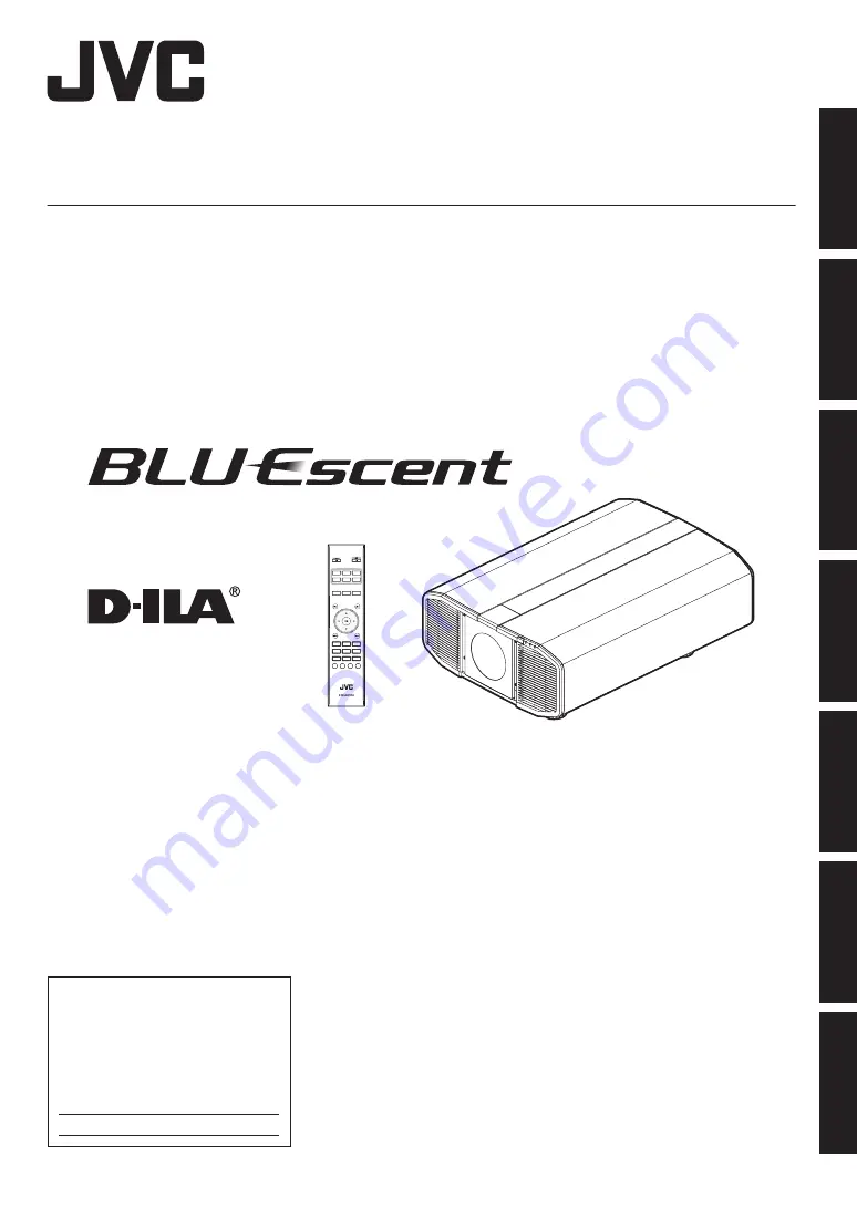
D-ILA Projector
DLA-VS4550
DLA-VS4600
DLA-VS4700
.
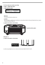
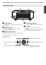
INPUT 1
DISPLAYPORT
INPUT 2
DUAL
NATURAL
DYNAMIC
INPUT 4
INPUT 3
QUAD
LENS
AP.
PIC.
ADJ.
COLOR
TEMP.
GAMMA
USER5
USER6
USER4
USER2
USER3
USER1
LENS
CONTROL
MOTION
ENHANCE
C.M.D.
NAME
EDIT
.
For Customer use :
Enter below the serial No. which is
located on the side of the cabinet.
Retain this information for future
reference.
DLA-VS4550,
DLA-VS4600,
DLA-VS4700
Model No.
Serial No.
INSTRUCTIONS
B5A-2671-20
Getting Started
Set up
Operate
Adjust/Set
Maintenance
Troubleshooting
Others


