background image

 Operation

Others

Preparation

Getti

ng Started

Maintenance

0710TTH-AO-AO

© 2010 Victor Company of Japan, Limited

DLA-X3

DLA-X7

DLA-X9

D-ILA

 PROJECT

OR

PROYECT

OR D-ILA

PROJECTEUR D-ILA

     FOR SERVICING(Only in U.S.A)

   TO OUR VALUED CUSTOMER


THANK YOU FOR PURCHASING THIS JVC PRODUCT.

      WE WANT TO HELP YOU ACHINEVE A PERFECT EXPERINCE.


NEED HELP ON HOW TO HOOK UP?

              NEED ASSISTANCE ON HOW TO OPERATE?
             NEED TO LOCATE A JVC SERVICE CENTER?
                    LIKE TO PURCHACE ACCESSORIES?

                           IS HERE TO HELP!
           

TOLL FREE: 1(800)252-5722

                    http://www.jvc.com

      Remember to retain your Bill of Sale for Warranty Service.

                    DO not attempt to service the product yourself 
                    

                    Caution


To prevent electrical shock,do not open the cabinet.

                      There are no user serviceable parts inside.
                      Please refer to qualified service personnel for repairs.


DLA-X3/DLA-X7/DLA-X9

For Customer use :

Enter below the serial No. which is 
located on the side of the cabinet.
Retain this information for future
reference.

Model No.   DLA-X7

 DLA-X9

  DLA-X3

Serial No.

Instrucción para el cliente :

Introduzca a continuación el nº de 

serie que aparece en la parte 

inferior lateral de la caja. Conserve 

esta información como referencia 

para uso ulterior.

Modelo Nº   DLA-X7

 DLA-X9

  DLA-X3

Nº de serie

Pour utilisation par le client :

Entrer ci-dessous le N° de série qui

est situé sous le boîtier. Garder  

cette information comme référence


pour le futur.

N° de modèle   DLA-

X7

        DLA-X9

         DLA-X3

N° de série

INSTRUCTIONS

MANUEL D’INSTRUCTIONS


MANUAL DE INSTRUCCIONES

D-ILA PROJECTOR
PROJECTEUR D-ILA
PROYECTOR D-ILA

DLA-X3
DLA-X7
DLA-X9

BACK

HIDE

LIGHT

LENS AP.

C.M.D

INFO.

HDMI 1

STAND BY

ASPECT

HDMI 2

ANAMO

COMP.

COMPONENT

LENS

CONTROL

MENU

GAMMA

C.TEMP.

C.SPACE

PIC.ADJ.

      ON

FILM

OINEMA

NATURAL

STAGE

3D

USER1

COLOR COLOR

TEMP. SPACE ADJUST

USER2

USER3

ANIME

PICTURE

CINEMA

PC010680299-1

ENGLISH  FRANÇAIS  ESPAÑOL/CASTELLANO 

X7 X9

Summary of Contents for DLA-X3

Page 1: ...DLA X7 DLA X9 DLA X3 Nº de serie Pour utilisation par le client Entrer ci dessous le N de série qui est situé sous le boîtier Garder cette information comme référence pour le futur N de modèle DLA X7 DLA X9 DLA X3 N de série INSTRUCTIONS MANUEL D INSTRUCTIONS MANUAL DE INSTRUCCIONES D ILA PROJECTOR PROJECTEUR D ILA PROYECTOR D ILA DLA X3 DLA X7 DLA X9 BACK HIDE LIGHT LENS AP C M D INFO HDMI 1 STAN...

Page 2: ...Connect the equipment into an outlet on a circuit different from that to which the receiver is connected Consult the dealer or an experienced radio TV technician for help WARNING TO PREVENT FIRE OR SHOCK HAZARDS DO NOT EXPOSE THIS APPLIANCE TO RAIN OR MOISTURE WARNING THIS APPARATUS MUST BE EARTHED CAUTION To reduce the risk of electric shock do not remove cover Refer servicing to qualified servic...

Page 3: ...When replacement parts are required be sure the service technician has used replacement parts specified by the manufacturer or with same characteristics as the original part Unauthorized substitutions may result in fire electric shock or other hazards Upon completion of any service or repairs to this product ask the service technician to perform safety checks to determine that the product is in pr...

Page 4: ... When fixing the unit to the ceiling Please note that we do not take any responsibility even during the warranty period if the product is damaged due to use of metal fixtures used for fixation to the ceiling other than our own or if the installation environment of said metal fixtures is not appropriate If the unit is suspended from the ceiling during use please be careful in regard to the ambient ...

Page 5: ...his product are colored Vert et jaune in accordance with the following cord Green and yellow Blue Brown As these colors may not correspond with the colored making identifying the terminals in your plug proceed as follows The wire which is colored green and yellow must be connected to the terminal which is marked M with the letter E or the safety earth or colored green or green and yellow The wire ...

Page 6: ...tteriesymbols gibt an dass diese Batterie Blei enthält Informations relatives à l élimination des appareils et des piles usagés à l intention des utilisateurs Union européenne seulement Si ces symboles figurent sur les produits cela signifie qu ils ne doivent pas être jetés comme déchets ménagers Si vous voulez jeter ce produit ou cette pile veuillez considérer le système de collection de déc hets...

Page 7: ... il simbolo delle batter ie indica che questa batteria contiene piombo Informação para os utilizadores acerca da eliminação de equipamento usado e pilhas Apenas União Europeia Estes símbolos indicam que o equipamento com estes símbolos não deve ser eliminado juntamente com o restante lixo doméstico Se p retende eliminar o produto ou a pilha utilize os sistemas de recolha ou instalações para uma re...

Page 8: ... Pb merk intä tarkoit taa että akku sisältää lyijyä Information för användare gällande bortskaffning av gammal utrustning och batterier Endast den Europeiska unionen Dessa symboler indikerar att utrustning med dessa symboler inte ska hanteras som vanligt hushållsavfall Om du vill bortsk affa produkten eller batteriet ska du använda uppsamlingssystem eller inrättningar för lämplig återvinning Obser...

Page 9: ...e olovo Informacje dla użytkowników dotyczące poz bywania się zużytego sprzętu i baterii Tylko kraje Unii Europejskiej Te symbole oznaczają że sprzę tu nie należy wyr zucać razem z odpadami gospodarczymi Jeśli trzeba po zbyć się tego produktu lub ba terii proszę skorzystać z systemu odbioru lub urządzeń do zbió rki odpadów elektronicznych w celu odpowiedniego ponowne go ich przetworzenia Uwaga Ozn...

Page 10: ...screen Also JVC front projectors are the first in the world 1 to have gained the THX 3D Display Certification 2 by THX Ltd In addition the certification standards were established with the aim to faithfully reproduce images at home according to the intentions of the film director during playback of 2D or 3D images and they are a proof of high definition and high image quality indicating that a cer...

Page 11: ...11 Getting Started ENGLISH For detail information about ISF please refer web site http www imagingscience com ...

Page 12: ...r cord provided 31 Operation Basic Operation 32 Basic operation procedures 32 Frequently used useful functions 34 Setting the Screen Size 34 Masking the Surrounding Area of an Image 35 Temporary turning off of the video 36 Adjustment of the keystone correction 36 Adjustments and settings in the menu 37 Structure of the menu hierarchy summary 37 Menu operation button 43 Menu operation procedure 44 ...

Page 13: ...1 piece Power Cord For the EU market 2 m 1 piece Power Cord For the UK market 2 m 1 piece Instruction manual warranty card and other printed material are also included Optional Accessories Check the Accessories Please check with your authorized dealer for details Replacement Lamp PK L2210U Replacement Filter PC010661199 3D Glasses PK AG1 B 3D Synchro Emitter PK EM1 ...

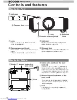
Page 14: ...Manual button for lens cover Inlets at 3 points on the rear bottom In order to cool the inside of the unit air is let inside Do not block or prevent the outflow of hot air Doing so could lead to failure of the unit There are inlets at two points on the right and left sides of the rear side Reference page 15 Manual operation button of the lens cover The lens cover can be opened when pressed down It...

Page 15: ...ng illustration Control panel for more details Light receiving section of the remote control rear Please aim the remote control at this section when using There is also a light receiving section at the rear Power input terminal This is the power input terminal It is connected via the supplied power cord Reference page 31 To turn on off the power To switch input To select or confirm Up button Right...

Page 16: ...d as described above Reference page 73 The display the indicator lights They display flashing of the indicator STAND BY Light on Red Duringstandby LAMP WARNING STANDBY ON STAND BYLight on Green LAMP WARNING STANDBY ON STAND BY Blinking Red Duringcooldown Whileactivatingthelamp about1minute LAMP WARNING STANDBY ON STAND BY Blinking Green Duringimageprojection LAMP WARNING STANDBY ON All Off When Hi...

Page 17: ...nit until it cools down After that turn on the power again 2 times Cooling fan stops 3 times Internal temperature is too high 4 times External temperature is too high orange red Simultaneous flashing Abnormal electrical circuit 2 times 3 times 4 times If something is wrong with the automatic lens cover Check that an impact shock has not occurred during operation Check that the lamp unit and lamp c...

Page 18: ...d with devices which are equipped with signal output etc Reference page 27 3D SYNCHRO terminal 3D synchro emitter it is connected to the PK EM1 sold separately when enjoying 3D video contents Reference page 28 PC terminal D Sub 15 pin X7 X9 This is an input term used for Personal Computer PC signals only RGB video signals and sync signals Use to connect a computer display output terminal etc Refer...

Page 19: ...lect or confirm To return to the previous menu Reference page 43 To switch picture mode Color Profile Sequentially switched picture adjust items such as contrast and brightness The switching items are not the same for different models or different picture modes To set gamma To adjust color temperature To display close the menu Reference page 43 To hide the image temporarily Reference page 36 Lens ...

Page 20: ...unit might cause shadows on the screen heat haze phenomenon Moreover when it is enclosed in a space as shown in the following illustration please make sure that the enclosed interior has the same temperature as the outside High temperatures might lead to failure of the unit This unit uses a projection lamp which will get hot when in use Please refrain from projecting in the following circumstances...

Page 21: ...not set within the above mentioned range Approximately 34 maximum of the projected image Approximately 34 maximum of the projected image Approximately 80 maximum of the projected image Approximately 80 maximum of the projected image 90 80 70 60 50 40 30 20 10 0 10 20 30 40 Horizontal lens shift Vertical lens shift Maximum Up Down shift varies with the amount of Left Right shift Likewise maximum Le...

Page 22: ...ting Depth of the screw holes screw length is 23 mm Use screws shorter than 23 mm but longer than 13 mm Using other screws will result in malfunctioning or cause the unit to drop When mounting to a pedestal ensure sufficient space foot height of 10 mm or higher around the unit so that the air inlets are not blocked Do not tilt this unit more than 5 degrees from side to side when using Regardless w...

Page 23: ...le 60 Approx 0 7 1 3m Approx 1 78m to Approx 3 66m 70 Approx 0 9 1 5m Approx 2 09m to Approx 4 28m 80 Approx 1 0 1 8m Approx 2 40m to Approx 4 89m 90 Approx 1 1 2 0m Approx 2 70m to Approx 5 51m 100 Approx 1 2 2 2m Approx 3 01m to Approx 6 13m 110 Approx 1 4 2 4m Approx 3 31m to Approx 6 75m 120 Approx 1 5 2 7m Approx 3 62m to Approx 7 36m 130 Approx 1 6 2 9m Approx 3 92m to Approx 7 98m Effective...

Page 24: ... X 480 37 900 72 000 31 500 832 520 640 480 3 VGA 75 640 X 480 37 500 75 000 31 500 840 500 640 480 4 VGA 85 640 X 480 43 300 85 000 36 000 832 509 640 480 5 SVGA 56 800 X 600 35 200 56 000 36 000 1024 625 800 600 6 SVGA 60 800 X 600 37 900 60 000 40 000 1056 628 800 600 7 SVGA 72 800 X 600 48 100 72 000 50 000 1040 666 800 600 8 SVGA 75 800 X 600 46 900 75 000 49 500 1056 625 800 600 9 SVGA 85 80...

Page 25: ...one that is HDMI approved It may not be possible to connect to this unit depending on the dimension of the connector cover of the cables to be connected 1 HDMI 2 RS 232 C 3D CR PR CB PB Y SYNCHRO PC TRIGGER REMOTE CONTROL STANDBY ON MENU BACK INPUT OK To connect via HDMI terminal Reference page 26 Connection to the unit To connect via video terminal Reference page 27 Connection by LAN terminal Ref...

Page 26: ...th in compliance with the HDMI standard a 340MHz cable is recommended In case a cable is used for transmission bandwidth of 75MHz it is recommended to choose 1080i or less for the transmitting equipment If the video is not displayed try to reduce the length of the cable or lowering the resolution of the video transmitting equipment If noise is produced take PCs desktop computer away from this unit...

Page 27: ...nput terminals Component video cable sold separately Connecting via RGB Video Cable Set COMP in the setting menu to RGB Reference page 52 For information on compatible input signals see Specifications Reference page 73 1 HDMI 2 RS 232 C 3D CR PR CB PB Y SYNCHRO PC TRIGGER REMOTE CONTROL STANDBY ON MENU BACK INPUT OK This unit Device equipped with RGB output RGB video cable sold separately RGB vide...

Page 28: ...K This unit 3D synchro emitter This is a dedicated terminal for PK EM1 sold separately 3D glasses PK AG1 B is an optional device and is not included in the 3D synchro emitter Note that converting 2D images to 3D ones using the 3D feature of this product and playing them for commercial purposes or for broadcasting in public places may infringe the rights of authors protected under the copyright law...

Page 29: ...ices or injury Using beyond the rated value will cause malfunction Exercise adequate caution to prevent short circuit as the trigger terminal outputs a voltage of 12V The default is set to No output Please set it under the item Trigger of menu 5 Function Reference page 54 Screen Trigger cable sold separately Trigger input terminal Φ 3 5 1 HDMI 2 3D CR PR CB PB Y SYNCHRO PC TRIGGER REMOTE CONTROL S...

Page 30: ...ideo signal Please contact your network administrator for questions concerning the network connection Network HUB Server 1 HDMI 2 RS 232 C 3D CR PR CB PB Y SYNCHRO PC TRIGGER REMOTE CONTROL STANDBY ON MENU BACK INPUT OK Connected by a REMOTE terminal This unit External infrared sensor sold separately For an external infrared sensor and connecting cable please contact your dealer or a JVC service c...

Page 31: ...r input terminal 2 Connect to the power outlet As the amount of electrical energy for this unit is large please connect it directly into the wall outlet When you are not using the equipment please unplug the power cord Connect it only with the provided power cord Do not use voltage other than the indicated power voltage Do not damage break or modify the power cord Moreover the power cord will be d...

Page 32: ...e input mode by pressing the INPUT button on the unit Reference page 15 HDMI 1 HDMI 2 COMP PC 2 Play back the selected device Adjust the zoom screen size BACK Back Operate Select Exit MENU Zoom Lens Control LENS Adjust accordingly by pressing the up down buttons 4 Adjust the focus focal point Adjust accordingly by pressing the up down buttons BACK Back Operate Select Exit MENU Focus Lens Control L...

Page 33: ...r cannot be turned off within approximately 90 seconds after it has been turned on Start operation only after 90 seconds time You can also press the button on the unit to turn off the power Reference page 15 Pull out the power plug when the unit will not be used for a prolonged time About Cool Down mode MEMO The Cool Down mode is a function to cool down the lamp for approximately 60 seconds after ...

Page 34: ...me Top and bottom of the image are missing SDTV 4 3 Image recorded in landscape black bands on top and bottom of DVD software Aspect Ratio Same Small image is projected Aspect Ratio Landscape Image is stretched horizontally Aspect Ratio Same Most appropriate screen size Depending on the input image selecting 4 3 may result in a vertically stretched image while selecting 16 9 provides you with the ...

Page 35: ...ignal 3 Set a mask value Select Exit MENU BACK Back Select Operate Aspect Video Progressive HDMI COMP Auto PC Picture Position 16 9 5 5 Mask 2 5 5 Off Custom Input Signal Example When the Mask value is changed from Off 5 3 To end MENU Images for which quality at the outer area has deteriorated can be projected by masking hiding the surrounding area of the projected image 1 Image for which quality ...

Page 36: ...ary turning off of the video In regards to the projection plane any occurring keystone distortion is adjusted in case the installation location is inclined 2 Select Installation Keystone Selec Confirm Exit MENU BACK Back Select Operate Pixel Adjust Installation Lens Control Anamorphic Screen Adjust Black Level Installation Style Front Off Keystone X7 X9 BACK HIDE LIGHT LENS AP C M D PC HDMI 1 STAN...

Page 37: ...ion of the picture quality submenu Picture Adjust Reset Advanced Exit MENU BACK Back Select Operate Color Temp Gamma Film Tone Contrast Brightness Color Tint 0 0 0 0 Color Profile Picture Mode Film Film1 Xenon1 Film1 Picture Adjust Reset Exit MENU BACK Back Select Operate Color Temp Gamma Advanced Contrast Brightness Color Tint 0 0 0 0 Picture Mode Natural 6500K Normal Exit MENU BACK Back Select O...

Page 38: ...reen Adjust Black Level Installation Style Front Off Exit MENU BACK Back Select Operate Display Setup Back Color Menu Display Menu Position On Line Display 5sec Source Display On Logo On Language English Black 4 Display Setup 3 Installation To 3 Layers and organization of the installation submenu Continue to the next Continued from the previous page COM COM ...

Page 39: ...er Lamp Reset High Altitude Mode Off Off Off Function Exit MENU BACK Back Select Operate 160H HDMI 2 1080p60 10bit Input Source Deep Color Lamp Time Information Exit MENU BACK Back Select Operate Lamp Time Deep Color 160H PC 1920X1080 Information Resolution 67 50kHz H Frequency 60 0Hz V Frequency Input 8bit To 5 Layers and organization of the function submenu 6 Information 5 Function X7 X9 X7 X9 X...

Page 40: ...Operate Color Temp Gamma Advanced Contrast Brightness Color Tint 0 0 0 0 Picture Mode Natural 6500K Normal Picture Adjust Exit MENU BACK Back Select Operate Advanced 0 Lens Aperture CMD Demo Clear Motion Drive Color Management Custom Gamma NR Lamp Power Sharpness Off Off Normal Picture Adjust Exit MENU BACK Back Select Operate Advanced 0 Lens Aperture CMD Demo Clear Motion Drive Custom Gamma Color...

Page 41: ...pect Video Progressive HDMI COMP Mask Auto Picture Position 16 9 Off Input Signal Exit MENU BACK Back Select Operate Input Signal COMP Y Pb Cb Pr Cr Color Space Exit MENU BACK Back Select Operate Level Check Input Signal HDMI Off Control with HDMI Auto Color Space Auto 3D Format Enhanced Input Exit MENU BACK Back Select Operate Input Signal PC 16 Phase 2200 Tracking Picture Position Auto Alignment...

Page 42: ...92 168 0 254 255 255 255 0 192 168 0 2 Exit MENU BACK Back Select Operate Pixel Adjust Installation Lens Control Keystone Anamorphic Screen Adjust Black Level Installation Style Front Off Exit MENU BACK Back Select Operate Lock Off Zoom Shift On Image Pattern Auto Lens Cover Installation Lens Control Focus Exit MENU BACK Back Select Operate Horiz Green Horiz Blue Installation Pixel Adjust Vert Red...

Page 43: ...s turned off when the main menu screen is shown This unit Remote Control Displaying the main menu and the submenu Select an adjustment item in the menu Set the setting value of the selected adjustment item The adjusted setting value is immediately reflected in the image Selection of a displayed sub menu item Selection of an item in the menu Operate the menu by use of the buttons on the main body o...

Page 44: ...s vary depending on the input signal and the picture mode See Content menu on the next page for more details 4 Press the cursor to select the items to adjust If the name of a submenu item is displayed in a dimmed manner it cannot be selected 5 Press cursor to change settings 6 After adjusting press BACK Every time it is pressed you will return to the respective previous menu screen 7 Repeat steps ...

Page 45: ...s selected based on the video production We recommend to match the color profile of the video you want to watch If you select Off it is impossible to perform any picture adjust for other color temp other than Lamp power and Lens aperture under Advance and also not gamma or sharpness Setting Film 1 Film 2 Cinema 1 Cinema 2 Standard Anime 1 Anime 2 Video Vivid Adobe Stage 3D Off Depending on the pic...

Page 46: ...ven more focused on tone for the gamma of Film 1 Film 4 This is a gamma curve that emphasizes more contrast for the gamma of Film 2 A B C D cannot be set if the Picture Mode is 3D A B C D In regard to normal gamma this is a gamma curve focused on tone This is a gamma curve for the film s unique S curve This is a gamma curve that in regard to the gamma of B emphasized even more the feeling of contr...

Page 47: ...ces a well balanced video image Settings Between reddish 5500 9500 bluish in steps of 500K 6500 Xenon1 Xenon2 Xenon3 This reproduces the color temp characteristics of a xenon lamp being used in cinemas A light source color that is emitted by a film projector A light source color emitted by a projector used for digital cinema A light source color that looks cooler than that of the Xenon2 Offset Xen...

Page 48: ...nd save it To 1 2 3 Color Management of the submenu Clear Motion Drive It improves video images with fast movements to produce clear video images with little residual image retention For PC and 3D signals the Clear motion Drive cannot be set Moreover the images in some scenes may be distorted In such a case please select Off Settings Off Mode 1 Mode 2 Mode 3 Mode 4 Film motion Off Off Off Mode 1 B...

Page 49: ...f the picture adjust and then save it Please adjust to your preference Initial values of Custom 1 2 and 3 are the same as for Normal Please refer to the figure at the bottom of the menu in two frames for adjustment It is recommended that you read Gamma Curve page reference 56 for hints about adjustment Correction Value You can choose to add the underlying gamma curve adjustment Can choose any sett...

Page 50: ...his can be set if one selects the PC terminal to the submenu 2 3 PC Picture Position Please adjust if the edges of the picture are partially missing due to the timing of horizontal and vertical synchronization signals The value of the picture position depends on the input signal Depending on the input signal it may be the case that not everything of the video image is displayed When there is a 3D ...

Page 51: ... Sets the dynamic range of the input video images scale Dark and bright areas which are not matched to the range might get brighter or darker If you are unsure of the input signal dynamic range please check under Level Check Settings Standard Enhance Super White Standard Standard It gets set if the dynamic image range of the gradation level of the input image is set to 16 235 In case of a video si...

Page 52: ...he size and display of the horizontal direction and display area of the video images Depending on the signal there is normally no need to be adjusted Phase Adjusts the flickering and blur of the video images Depending on the signal there is normally no need to adjustment Picture Position Adjust the display of the picture position Horiz Adjusts the horiz of the video image Vert Adjusts the vertical...

Page 53: ... focus Zoom This function is used to adjust the zoom Shift This function is used to adjust the shift Lens Cover This function is used to set if the lens cover should be linked with a power supply for opening closing or if it should be left open Settings Auto Open Auto Auto This opens closes the lens cover when it is linked to on off of a power supply Open Regardless if the power supply is on on of...

Page 54: ...me for the menu to be displayed Settings 15 sec On On 15 sec If there is no menu operation for 15 seconds the menu display vanishes On Display always Line Display Configures if input is displayed or not when input is switched value 5 sec Off 5 sec 5 sec Displays for 5 seconds Off Not displayed Source Display Configures whether or not to display the signal when the input is switched Settings On Off...

Page 55: ...CP server The automatic retrieval starts with the Set within the menu Off The network settings are being done manually IP Address Sets the IP address 192 168 0 2 Subnet Mask Sets the subnet mask 255 255 255 0 Default Gateway Sets the default gateway 192 168 0 254 MAC Address Displays the MAC address of the unit Set 5 1 Reflects the network setting 6 Information Displays upon HDMI COMP input Input ...

Page 56: ...the video images A low angle of inclination leads on the contrary to the difference in that area becoming smaller so that the video images are harder to distinguish If it is im possible to get an inclination angle so that it is chosen to become horizontal the gap in that area vanished and it might be impossible to distinguish the video images The light output A B C Input sig nal value 100 100 0 0 ...

Page 57: ...virtual images 立体映像 Eye Video images seen with the right eye Video images seen with the left eye Stereoscopic video image Binocular parallax Difference of the view on a single object when seen from the left and right eyes respectively CAUTION Please stop watching at once if you do not feel well and consult a physician if necessary People who already have a kind of photosensitivity sufferers from h...

Page 58: ...e and discomfort Left eye image Right eye image Stereoscopic video image CAUTION In most cases 3D images taken or produced are horizontally arranged respectively If these images were not horizontally arranged for left and right eye movement when watching the brain could not perceive a stereoscopic image but would still recognize a double image As such video images can cause 3D sickness please do n...

Page 59: ...sses with infrared rays Left eye image Right eye image Eye Close Open Video image projection with the projector frame sequential method 3D glasses CAUTION As the video images for the left and right side flash alternatively when displayed we urge you to refrain from looking at the screen with naked eyes When viewed with several people please prepare glasses for them These 3D glasses are only for th...

Page 60: ...o not use flammable air duster to clean the internal parts of the unit This may cause fire Lamp replacement procedure MEMO Usable Lamp Life Purchasing the Lamp Unit When using the Lamp Power set at Normal the lifetime of the lamp will be approximately 3000 hours This is an average lifetime and cannot be guaranteed The lamp life may not reach 3000 hours depending on the operating conditions When th...

Page 61: ...face of a new lamp This may shorten the lamp life and cause lamp blowout MEMO After Replacing the Lamp Do not place the removed lamp unit at locations that is reachable by children or near combustible items Dispose used lamp units in the same way as fluorescent lamps Follow your local community rules for disposal 5 6 Tighten the screws with a screwdriver Insert the top part with 2 claws of the lam...

Page 62: ...LENS CONTROL MENU GAMMA P FILE COLOR ADJ PIC ON FILM NATURAL STAGE 3D USER1 USER2 THX ANIME CINEMA PICTURE MODE INPUT TEMP COLOR MENU Picture Adjust Reset Advanced Exit MENU BACK Back Select Operate Color Temp Gamma Film Tone Contrast Brightness Color Tint 0 0 0 0 Color Profile Picture Mode Film Film1 Xenon1 Film1 Display the setting menu Select Function Lamp Reset Exit MENU BACK Back Select Opera...

Page 63: ...ILE COLOR ADJ PIC ON FILM NATURAL STAGE 3D USER1 USER2 THX ANIME CINEMA PICTURE MODE INPUT TEMP COLOR X7 X9 Reset the lamp time by remote control 1 2 Insert the power plug to the power outlet Red Lights Must operate with the remote control in the standby mode the projector is powered but is not turned on Press in the order as shown Press each button within 2 second intervals and press the last but...

Page 64: ...m cleaner or air duster The filter is soft and may be damaged Reinstall the inner filter 3 CAUTION Pull the power plug from the power outlet Please turn this unit and if you put in on a bed or a table first place something soft like a piece of cloth below Then you can put it on top of it Otherwise it may cause scratches on this unit If the filter is damaged or too dirty to be cleaned MEMO Replace ...

Page 65: ... on the power again Reference page 33 Video image does not appear Is the correct external input selected Select the correct external input Reference page 32 Is the AV device properly connected Connect the AV device properly Reference page 25 to 30 Is the power of the AV device turned on Turn on the power of the AV device and play the video Reference page 32 Are the correct signals being output fro...

Page 66: ...g menu to Off Reference page 35 Reference page 51 Is the display out of position Alter the Picture Position value in the setting menu to ensure that images are not missing Reference page 50 Projected image is dark Is the lamp near exhaustion Check the lamp time on the information menu Prepare a new lamp unit or replace as soon as possible when the lamp is near exhaustion Reference page 60 to 63 Th...

Page 67: ...l that cannot be used in this unit has been input Input video signals that can be used The names of input terminals such as COMP will be displayed in yellow BACK Back Lamp replacement This message is displayed when the accumulated lamp time has exceeded 2900 hours To clear the message press the Back button Get ready a new lamp unit and replace as soon as possible Reset the lamp time after replacin...

Page 68: ...o receive PJACK Please perform this operation after confirming the operating status of the projector again after establishment of a TCP connection if you cannot send within 5 seconds PJ_NG or could not receive PJNAK RS 232C Specifications Pin No Signal Function Signal Direction 2 RxD Receive data PC This unit 3 TxD Transmit data This unit PC 5 GND Signal ground 1 4 6 9 N C Mode Non synchronous Cha...

Page 69: ...t PC When the command is accepted without error it returns to PC Unit ID This code specifies the unit The binary code is fixed at 8901 Command and data Operating command and data Binary code Command Type Description 0000 Connection check Check whether communication is available between this unit and the PC during standby 5057 Power supply During standby 31 Turn on the power During power on 30 Turn...

Page 70: ...n name Binary code 37 33 30 31 NATURAL 37 33 36 41 37 33 30 32 USER 1 37 33 36 43 BACK 37 33 30 33 USER 2 37 33 36 44 ON 37 33 30 35 USER 3 37 33 36 45 STAND BY 37 33 30 36 THX 37 33 36 46 HIDE 37 33 31 44 HDMI 1 37 33 37 30 LENS AP 37 33 32 30 HDMI 2 37 33 37 31 MENU 37 33 32 45 PIC ADJ 37 33 37 32 OK 37 33 32 46 INFO 37 33 37 34 LENS CONTROL 37 33 33 30 GAMMA 37 33 37 35 37 33 33 34 C TEMP 37 33...

Page 71: ...is unit 21 89 01 49 50 32 0A This unit PC 06 89 01 49 50 0A When video input is set to component Remote Control MENU PC This unit 21 89 01 52 43 37 33 32 45 0A This unit PC 06 89 01 52 43 0A When the same operation as pressing the MENU button on the remote control is made Reference command Type Command Description Power On PC This unit 3F 89 01 50 57 0A This unit PC 06 89 01 50 57 0A This unit PC ...

Page 72: ...ent varies greatly depending on the usage and environment Please consult your authorized dealer for replacement Maintenance Procedures Dirt on the cabinet Gently clean dirt on the cabinet with a soft cloth In the case of heavy soiling soak a cloth in water wring dry and wipe followed by wiping again with a dry cloth Pay attention to the following as the cabinet may deteriorate in condition or pain...

Page 73: ...rminal Video Input 1 system RCA pin jack 3 Y 1 0Vp p 75Ω Pb Cb Pr Cr 0 7Vp p 75Ω Also supports R G B Sync on G HDMI Input 2 system HDMI 19 pin 2 HDCP compliant 4 Compatible with the HDMIv1 4a standard 5 PC Input 1 system D Sub 15 pin VGA Output terminal Trigger terminal 1 system Φ 3 5mmDC Power Jack DC OUT 12V 0 1A 3D synchro 3D synchro emitter dedicated terminal 1 system mini DIN 3pin Control ter...

Page 74: ... 01 or less of the pixels are either missing or would remain permanently lit up 4 HDCP is the abbreviation for High bandwidth Digital Content Protection system The image of HDMI input terminal may not be displayed due to HDCP specification change 5 Ethermet is not supported Design and specifications are subject to change without prior notice Please note that some of the pictures and illustrations ...

Page 75: ...ge 50 Screen Size Distance Chart Page 23 Aspect Video and aspect PC of 2 Input Signal Page 50 Zoom of 3 1 Lens Control Page 53 Mask Mask of 2 Input Signal Page51 Screen Menu Table Menu Structure Page 37 1 Picture Adjust Page 37 40 Index 2 Input Signal Page 37 41 3 Installation Page 38 42 4 Display Setup Page 38 5 Function Page 39 42 6 Information Page 39 Operating procedure Page 44 Batteries Types...

Page 76: ...of 1 2 Advanced Page 49 Lamp reset of 5 Function Page 55 How to reset the lamp time Page 62 63 Notes of Caution Page 4 Remote control Button placement Page 19 Instructions Page 23 See Dry battery section Lens 3 1 Lens Control Page 53 Focus of 3 1 Lens Control Page 53 Zoom of 3 1 Lens Control Page 53 Shift of 3 1 Lens Control Page 53 Cleaning the lens Page 72 Index continued ...

Page 77: ...78 Others 5 MEMO ...
Page 78: ...GLISH Dimensions Unit mm 455 5 337 59 227 5 Φ60 24 103 5 178 5 290 472 91 110 32 110 92 Lens center Lamp cover Top Surface Front Bottom Surface Back Surface Connection terminal section of the illustration is X7 X9 ...

Page 79: ...ED HELP ON HOW TO HOOK UP NEED ASSISTANCE ON HOW TO OPERATE NEED TO LOCATE A JVC SERVICE CENTER LIKE TO PURCHACE ACCESSORIES IS HERE TO HELP TOLL FREE 1 800 252 5722 http www jvc com Remember to retain your Bill of Sale for Warranty Service DO not attempt to service the product yourself Caution To prevent electrical shock do not open the cabinet There are no user serviceable parts inside Please re...

Reviews: