background image

3

SAFETY PRECAUTIONS

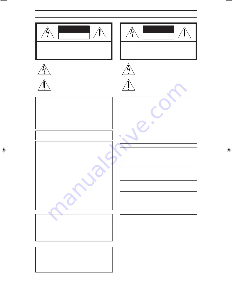
CAUTION

RISK OF ELECTRIC SHOCK

DO NOT OPEN

CAUTION: TO REDUCE THE RISK OF ELECTRIC SHOCK,

DO NOT REMOVE COVER (OR BACK).

NO USER-SERVICEABLE PARTS INSIDE.

REFER SERVICING TO QUALIFIED SERVICE PERSONNEL

ATTENTION

RISQUE D’ELECTROCUTION

NE PAS OUVRIR

ATTENTION: POUR EVITER TOUT RISQUE D’ELECTROCUTION

NE PAS OUVRIR LE BOITER.

AUCUNE PIECE INTERIEURE N’EST

A REGLER PAR L’UTILISATEUR.

SE REFERER A UN AGENT QUALIFIE EN CAS DE PROBLEME.

Le symbole de l’éclair à l’intérieur d’un triangle équilatéral est
destiné à alerter l’utilisateur sur la présence d’une “tension
dangereuse” non isolée dans le boîtier du produit. Cette
tension est suffisante pour provoquer l’électrocution de
personnes.

Le point d’exclamation à l’intérieur d’un triangle équilatéral
est destiné à alerter l’utilisateur sur la présence d’opérations
d’entretien importantes au sujet desquelles des
renseignements se trouvent dans le manuel d’instructions.

*Ces symboles ne sont utilisés qu’aux Etats-Unis.

The lightning flash with arrowhead symbol, within an
equilateral triangle, is intended to alert the user to the
presence of uninsulated “dangerous voltage” within the
product’s enclosure that may be of sufficient magnitude
to constitute a risk of electric shock to persons.

The exclamation point within an equilateral triangle is
intended to alert the user to the presence of important
operating and maintenance (servicing) instructions in
the literature accompanying the appliance.

INFORMATION

for USA

This equipment has been tested and found to comply with
the limits for a Class A digital device, pursuant to Part 15
of the FCC Rules. These limits are designed to provide
reasonable protection against harmful interference when
the equipment is operated in a commercial environment.
This equipment generates, uses, and can radiate radio
frequency energy and, if not installed and used in
accordance with the instruction manual, may cause
harmful interference to radio communications. Operation
of this equipment in a residential area is likely to cause
harmful interference in which case the user will be
required to correct the interference at his own expense.

CAUTION

CHANGES OR MODIFICATIONS NOT APPROVED BY
JVC COULD VOID USER’S AUTHORITY TO
OPERATE THE EQUIPMENT.

NOTE:

The rating plate (serial number plate) is on the rear of the unit.

WARNING:
TO REDUCE THE RISK OF FIRE OR
ELECTRIC SHOCK, DO NOT EXPOSE THIS
APPLIANCE TO RAIN OR MOISTURE.

THIS DEVICE COMPLIES WITH PART 15 OF THE
FCC RULES. OPERATION IS SUBJECT TO THE
FOLLOWING TWO CONDITIONS: (1) THIS DEVICE
MAY NOT CAUSE HARMFUL INTERFERENCE, AND
(2) THIS DEVICE MUST ACCEPT ANY INTERFER-
ENCE RECEIVED, INCLUDING INTERFERENCE
THAT MAY CAUSE UNDESIRED OPERATION.

This unit should be used with 120 V AC only.

CAUTION:
To prevent electric shocks and fire hazards, DO
NOT use any other power source.

AVERTISSEMENT:
POUR EVITER LES RISQUES D’INCENDIE OU
D’ELECTROCUTION, NE PAS EXPOSER
L’APPAREIL A L’HUMIDITE OU A LA PLUIE.

Ce magnétoscope ne doit être utilisé que sur
du courant alternatif en 120 V.

ATTENTION:
Afin d’éviter tout resque d’incendie ou
d’électrocution, ne pas utiliser d’autres
sources d’alimentation électrique.

REMARQUE:

La plaque d’identification (numéro de série) se trouve
sur le panneau arrière de l’appareil.

WARNING:

The battery used in the DM-JV600U must be replaced
by a JVC authorized service dealer only.

INFORMATION 

for Canada

This Class A digital apparatus meets all requirements of
the Canadian Interference-Causing Equipment Regulations.
Cet appareil numérique de la classe A respecte toutes les
exigences du Reglement sur le matériel brouilleur de
Canada.

CAUTION

Use of controls or adjustments or performance of proce-
dures other than those specified herein may result in haz-
ardous radiation exposure.

Note

Place a cover on the terminal not in use.
Static may cause a malfunction or failure of the unit.

Summary of Contents for DM-JV600U

Page 1: ...f cabinet Retain this information for future reference Model No DM JV600U Serial No Thank you for purchasing this JVC product Before operating this unit please read the instructions carefully to ensure the best possible performance POWER ON OFF LST0159 001C This instruction book is made from 100 recycle paper ...

Page 2: ...t contact your electrician to replace your obsolete outlet Do not defeat the safety purpose of the grounding plug 11 For added protection for this product during a lightning storm or when it is left unattended and unused for long periods of time unplug it from the wall outlet and disconnect the antenna or cable system This will prevent damage to the product due to lightning and power line surges 1...

Page 3: ...gy and if not installed and used in accordance with the instruction manual may cause harmful interference to radio communications Operation of this equipment in a residential area is likely to cause harmful interference in which case the user will be required to correct the interference at his own expense CAUTION CHANGES OR MODIFICATIONS NOT APPROVED BY JVC COULD VOID USER S AUTHORITY TO OPERATE T...

Page 4: ...e compact size design it can be mounted to the EIA rack 3 2 Pull down feature By converting to the SMPTE292M 1080i 720p standard HDTV digital serial video signal input movie film image that is 24 frame per one second can also be compressed to high quality using 3 2 Pull down feature Equipped with ASI output terminal Video recording is possible by connecting to D VHS digital video recorder from JVC...

Page 5: ...ting to a Rack 10 Menu Flow Chart 11 Menu Setting 12 How to Change Menu Setting 16 Restoring the Default Menu Setting Value 17 Starting the Encoding 18 Checking Operation Status 20 Checking Error Log 21 Using the Administration Menu 22 Error Log 24 Setting the 3 2 Pulldown 26 Specifications 27 INTRODUCTION Table of Contents Others Names and Functions ...

Page 6: ...cal shock if water is spilt into the equipment Do not insert anything into the equipment It will result in fire and electrical shock if metal or inflammable object is inserted from the ventilation hole Transportation Turn off the power and unplug the power cord from AC outlet before transportation This may cause damage to power cord fire or electrical shock When moving or carrying the main unit do...

Page 7: ...tem of this unit will be displayed Following item About display 6 POWER indicator Light up in green during operation 7 FAULT indicator Light up in orange when error occurs on this unit About Display Normal display Press the 8 9 buttons Display the control set ting status of this unit Displays the current operation status Display the setting sta tus of how encoding will start Display the setting st...

Page 8: ... For the audio signal to be input to AES EBU IN terminal use the 48 kHz audio signal that is synchronized with video signal If Dolby Digital bitstream is inputted when the Audio Format under the Initial Param Menu is set as MPEG loud sound might be produced Make sure that DD PT is set before inputting Dolby Digital bitstream RS 232C Remote terminal D sub 9pin By connecting to the device for remote...

Page 9: ...OG VIDEO OUT Y Pb Pr AES EBU OUT VIDEO IN ASI OUT ASI OUT DVB ASI IN HDTV DECODER DM D4600U DM JV600U AC 120V 50 Hz 60 Hz Supplied power cord Monitor Speaker AMP DIGITAL VIDEO RECORDER SR VDA300U REF IN D1 AES EBU IN D1 signal REF signal HD SDI signal DIGITAL AUDIO signal DVB ASI signal DVB ASI signal ANALOG VIDEO signal DIGITAL AUDIO signal Dolby Digital bitstream POWER AC IN RS 232C 10BASE T AES...

Page 10: ...y making use of the hole on inner side of front panel this unit can be mounted to EIA rack When mounting this unit to rack mount the L shape bracket to both ends of the rack to ensure strength When mounting to the rack mount it in the way such that this unit will not protrude out from the rack The depth of the rack should be at least 700 mm Remove the foot Remove the front panel Mount this unit to...

Page 11: ...e Current operation status and error log can be confirmed Administrator menu Password is required to operate Page 22 Using the Administration Menu Page 12 Operate Param Menu Page 13 Initial Param Menu Page 16 How to Change Menu Setting Page 20 Checking Operation Status Page 17 Restoring the Default Menu Setting Value Page 21 Checking Error Log Video Rate Asp 32Pulldown Audio Mode Audio Rate Start ...

Page 12: ...form 3 2 Pulldown process automatically depends on the video signal OFF Does not perform 3 2 Pulldown process Page 26 Setting the 3 2 Pulldown Set the channel mode of the audio encoded signal Stereo Encode with stereo mode Single Encode with single channel mode monaural Set the bit rate of the encoded audio signal Start the encoding Page 18 Starting the Encoding Stop the encoding Page 19 Stop the ...

Page 13: ... with 720p 720p format Setting the Audio Format MPEG Encoding with MPEG Layer 2 DD PT Dolby Digital Pass Through Dolby Digital bitstream will be output in TS Format Select the input audio signal AES EBU Encode the audio signal input into AES EBU terminal on the rear panel EMB Encode the Embedded audio signal input into HD SDI IN terminal 9 on the rear panel This setting is meant for compensating t...

Page 14: ... be output Set the ID of PAT TS PAT TS ID is the Transport Stream ID within PAT PAT Program Association Table is the correspondences table of Program number and PMT PID Set the PMT Packet ID PMT Program Map Table is an index table that designates the various stream PIDs which constituted the program Set the PCR Packet ID PCR Program Clock Reference is clock data that is output periodically It is u...

Page 15: ...f Audio PES to ON Set the Original Copy of Audio PES Org Set the Audio PES to Original Copy Set the Audio PES to Copy Save the setting value of the menu and restart this unit Page 18 Starting the Encoding Return the setting value of the menu to default and restart this unit Page 17 Restoring the Default Menu Setting Value Item Setting value Content Initial Param Menu Audio Stream ID Video Copyrigh...

Page 16: ... Menu I n i t i a l P a r a m M e n u Control Mode Local HDTV ENCODER DM JV600U I n i t i a l P a r a m M e n u Control Mode Local I n i t i a l P a r a m M e n u Control Mode Remote I n i t i a l P a r a m M e n u Save Reboot N o w I n i t i a l i z i n g How to Change Menu Setting Memo Memo Caution Caution Press the ENTER button Main Menu screen will be displayed Press the 8 9 buttons Select the...

Page 17: ...DM JV600U N o w I n i t i a l i z i n g Configuration Menu Default Reboot Configuration Menu Default Reboot Restoring the Default Menu Setting Value Press the ENTER button Main Menu screen will be displayed Press the 8 9 buttons Select the Configuration Menu Press the ENTER button Configuration Menu screen will be displayed Press the 8 9 buttons Select the Default Reboot Press the ENTER button Exe...

Page 18: ...M e n u Star t Mode Auto I n i t i a l P a r a m M e n u Star t Mode Auto I n i t i a l P a r a m M e n u Save Reboot Starting the Encoding POWER ON OFF POWER FAULT MULTI FORMAT HIGH DEFINITION TELEVISION ENCODER ENTER ESC Display 8 9 buttons ENTER button ESC button Start the encoding automatically Press the ENTER button Display the Initial Param Menu screen according to steps 1 5 on Page 16 How t...

Page 19: ...Operate Param Menu Operate Param Menu Vi d e o R a t e 2 0 0 0 0 k b p s Operate Param Menu Stop Start the encoding manually Stop the encoding manually Press the ENTER button Main Menu screen will be displayed Press the 8 9 buttons Select the Configuration Menu and press the ENTER button Press the 8 9 buttons Select the Operate Param Menu and press the EN TER button Press the 8 9 buttons Select th...

Page 20: ...enu S t a t u s F a t a l e r r o r Indicate that the encoding is in standby status Indicates that fatal error has occurred Page 24 Error Log Checking Operation Status Press the ENTER button Main Menu screen will be displayed Press the 8 9 buttons Select the Status Menu Press the ENTER button Status Menu screen will be displayed Press the 8 9 buttons Current operation status will be displayed by s...

Page 21: ...u n n i n g Status Menu Log 00 Feb07 14 06 0001 system boot Checking Error Log Press the ENTER button Main Menu screen will be displayed Press the 8 9 buttons Select the Status Menu Press the ENTER button Status Menu screen will be displayed Press the 8 9 buttons Select the Log item and press the ENTER button Press the 8 9 buttons The error log stored will be displayed For detailed error log displ...

Page 22: ...TELEVISION ENCODER ENTER ESC Display 8 9 buttons ENTER button ESC button Press the ENTER button Main Menu screen will be displayed Press the 8 9 buttons Select the Administration Menu Press the ENTER button The Administration Menu screen will be displayed Press the 8 9 buttons Choose the Time item and press ENTER button Press the 8 9 Buttons Buttons Move the cursor to the highlight the places when...

Page 23: ...For the Year setting only the last 2 digits of the year will be used Setting the Display brightness Setting range is between 0 to 3 0 Brightest setting Displays the firmware version Displays the version of the µ code Displays the version of boot program Displays the version of MISC FPGA Displays the version of STC FPGA Displays the version of I O PWB Displays the version of I O VI PLD Displays the...

Page 24: ... control device communication has occurred The value of command and parameter created by control device communication is abnormal This unit has received action command when it is busy The synchronized signal cannot be de tected The detection of the synchronized signal has timed out when this unit restarts The video input signal is abnormal The audio input signal is abnormal Resync process has occu...

Page 25: ...o running error recover 00a8 enc software audio input error 00a9 enc software audio input error recover 00aa enc software audio running error 00ab enc software audio running error recover Cause of error The content of the internal parameter default parameter and others is ab normal FAN operation is abnormal The hardware of this unit is abnormal The software of this unit is abnormal The restart of ...

Page 26: ...own method the odd number frame is converted to 2 fields and the even num ber frame is converted to 3 fields With this feature it is possible to convert 2 frames into 5 fields which means that 24 frames could be converted into 60 fields Setting the 3 2 Pulldown Encoding image film material Film 1st scene 2nd scene 3rd scene 4th scene HDTV VTR ENCODER Field 1 Field 2 Field 1 Field 2 Field 1 Field 2...

Page 27: ...800 mVp p 75 Ω BNC unbalanced Channel 1 5 1 channel Sampling 48 kHz Bit rate 56 kbps to 640 kbps RS 232C 1 AC 120 V 50 Hz 60 Hz 70 W 0 6 A 5 C to 40 C 20 C to 60 C 30 to 80 Approx 10 k Dolby is a trademark of Dolby Laboratories Specifications and appearance of this unit are subject to change for improvement without prior notice Input signal Output signal Video encoding Audio encoding Video encodin...

Page 28: ...COMPANY OF JAPAN LIMITED is a registered trademark owned by VICTOR COMPANY OF JAPAN LTD is a registered trademark in Japan the U S A the U K and many other countries 2004 VICTOR COMPANY OF JAPAN LIMITED Printed in japan LST0159 001C ...

Reviews: