background image

22

 About the external control

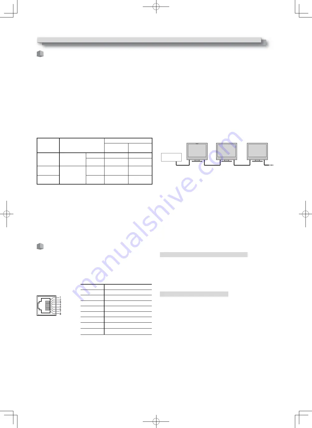
This monitor has three external control terminals.


Make/Trigger terminal

 (RJ-45): The following external control 

systems are available.

(

1) 

Make (make contact) system:


Controls the monitor by short-circuiting the corresponding pin 
terminal to the GND pin terminal, or disconnecting (opening) it.

(

2) 

Trigger (trigger) system: 


Controls the monitor by sending the pulse signal instantaneously 
to the corresponding pin terminal.

  ☞

 “Using the Make/Trigger system” below


RS-485 terminals

 (RJ-45): Controls the monitor with the RS-485 

system (

 “Using the serial communication” on page 23).


RS-232C terminal

 (D-sub 9-pin): Controls the monitor with the 

RS-232C system (

 “Using the serial communication” on page 23).

Set the following items of “Remote Setting” in Set-Up Menu 
according to the external control terminal and control system (


“Serial Type,” “Parallel Type”


on


page 18).

Control 

terminal

Control system

The settings of this unit

“Serial Type” 

setting

“Parallel 

Type” setting

Make/
Trigger 
terminal

Parallel Type

Make 

Make

Trigger

Trigger

RS-485 
terminal

Serial 
communication 

RS-485

RS485*

1

RS-232C 
terminal

RS-232C

RS232C*

1

*

1

  For a monitor connected to a personal computer etc, select the 

terminal the equipment is actually connected to. For other monitors, 
select “RS485.”

Control priority is as follows.

Make > Trigger = serial communication = buttons and menu on 
the monitor

  You can use external control even when “Control Lock” is set to 

“Volume Lock” or “All Lock” (

 page 19).

  When the monitor is off (on standby), external control is not 

available. But certain external controls (starting/terminating 
communication, turning on the monitor) are available through the 
serial communication (

 page 24).

<Make/Trigger system>

You can control the monitor by a personal computer or dedicated 
controller*

2

.

  “Using the Make/Trigger system” below.

*

2

  The controller is not commercially available. Consult your dealer if 

you need it.

<Serial communication>

RS-485 IN
or
RS-232C

RS-485 
OUT

RS-485
 IN

RS-485 
OUT

RS-485
 IN

RS-485 
OUT

  For the details, see page 23.

PC, etc.

External Control

 Using the Make/Trigger system

The Make/Trigger terminal is configured as follows. You can assign a 
function to each pin terminal in “Remote Setting” (

 “Pin1, Pin2, Pin3, 

Pin4, Pin5” in “Parallel Type” on page 18).

  You cannot change the functions assigned to the pin terminals 

from 6th to 8th.

Pin No.

Pin name

1

Pin1

2

Pin2

3

Pin3

4

Pin4

5

Pin5

This is a female terminal.

6

Tally*

1

7

Enable*

2

8

GND

*

1

  The 6th pin terminal controls turning on or off the tally lamp 

(available to control even when the 7th pin terminal is invalid).

*

2

  The 7th pin terminal makes the external control valid/invalid. Make 

sure to control the terminal by the Make system.

To assign the functions to the pin terminals

For the operation procedure, see page 12.

1


Select “Remote Setting” on the Set-Up Menu.

2


Set “Parallel Type” to “Set.”

3


Select a pin name (“Pin1” – “Pin5”) for which you want to assign a 
function, then select the function you want to assign.


For the selectable functions, see the table on page 23.

Operation of the external control

1


Set “Parallel Type” of “Remote Setting” to “Make” or “Trigger” in the 
Set-Up Menu.

2


Short-circuit the 7th pin terminal (ENABLE) to the 8th pin terminal 
(GND) so that the monitor can be controlled by the external control.

3


When the “Make” system is selected: Operate each function by short-
circuiting the corresponding pin terminal to the 8th pin terminal 
(GND) or opening it.


When the “Trigger” system is selected: Operate each function by 
pulse control, that is short-circuiting the corresponding pin terminal 
to the 8th pin terminal (GND) for about 1 second and opening it.

  When changing the input with Make system, activate the pin you 

want after deactivating the currently used pin.

  When selecting the “Trigger” system, you can operate only one 

function at a time. Operate the functions one by one.

DTE21L417L4G̲EN̲1.indb   22

12.2.24   4:01:07 PM

Summary of Contents for DT-E17L4G

Page 1: ... located on the rear of the cabinet Retain this information for future reference Model No Serial No DT E21L4 DT E17L4G MULTI FORMAT LCD MONITOR INSTRUCTIONS The illustration of the monitor is of DT E21L4 DT E21L4 DT E17L4G DTE21L417L4G EN 1 indb 1 12 2 24 4 00 57 PM ...

Page 2: ...nt parts specified by the manufacturer or equivalents Unauthorized substitutions may result in fire electric shock or other hazards Upon completion of any service or repairs to this product ask the service technician to perform safety checks to determine that the product is in proper operating condition Under the following conditions 1 Turn off the power 2 Unplug this product from the wall outlet ...

Page 3: ...ver place anything on the product Placing liquids naked flames cloths paper etc on the product may cause a fire Do not apply any strong shock to the LCD panel Do not hit any object against it or push it with a sharp pointed tool Do not put heavy objects on the product Do not step on or hang on the product FCC NOTICE CAUTION Changes or modifications not approved by JVC could void the user s authori...

Page 4: ...g the dust around the intakes may prevent proper temperature control and cause damage to the product Safety Precautions cont The LCD panel and backlight have life expectancy Due to the basic characteristics of the LCD panel an afterimage or uneven display may occur It is recommended that you change images occasionally activate the power saving function or often turn off the power to reduce the loa...

Page 5: ...l 8 Daily Operations 10 Front panel 10 Menu Configuration 12 The operation procedure 12 Menu Transition Diagram 13 Main Menu 14 Set Up Menu 17 External Control 22 About the external control 22 Using the Make Trigger system 22 Using the serial communication 23 Troubleshooting 25 Self check program 26 Specifications 27 General 27 LCD panel 27 Input output terminals 27 Dimensions 28 Available signals...

Page 6: ...d the bottom plate Screw holes C and E 5 Use no less than two commercially available screws no less than four screws on both sides for the screw holes 10 φ8 on the stand bottom plate to anchor the monitor Use screws having enough holding strength and resistance against external force of expected vibrations 10 φ8 CAUTION It is very dangerous not to anchor the stand with screws as this may cause not...

Page 7: ...vibrations and other external forces Mounting On Wooden Walls The weight of the unit should be borne by the wall posts or studs and these should be reinforced if insufficiently strong Do not install the Wall Mounting Unit on walls made of plasterboard or thin plywood Use the commercially sold screws best suited for the wall structure and material Mounting On Concrete Walls Use commercially sold wa...

Page 8: ...al When inputting audio into this terminal set Audio1 Assign or Audio2 Assign of the menu to HDMI Analog page 16 6 AUDIO MONITOR OUT terminals pin jack Output terminals for the analog audio signal The terminals emit the audio signals through the AUDIO IN terminal or EMBEDDED AUDIO signals through the E AUDIO HD SD SDI IN 1 or IN 2 input terminal The signal is output from this terminal only when th...

Page 9: ...ew holes for external battery attachment Attach external battery for DC 12 V power supply by using 2 screw holes Choose the appropriate screw holes from 1 2 or 3 according to the type of external battery Depending on the battery type Use the Anton Bauer Dionic 90 mount QR DXC M3A external battery CAUTION Do not use the external battery for DC 24 V power supply Use only the battery specified above ...

Page 10: ...tem cannot be controlled by the buttons on the front panel Remote On is displayed and the lamps do not light Tally lamp This lamp is controlled by the tally function of the MAKE TRIGGER terminal You can select the color of the tally lamp from Green or Red You can also select whether the whole lamp is turned on at once or whether it is turned on one half at a time Tally Setting in Set Up Menu on pa...

Page 11: ...d use the buttons The Volume Embedded Audio screen appears The Volume Embedded Audio screen disappears automatically is no operations are made for about 30 seconds 2 Use the buttons to select the left and right channels L ch R ch 3 Use the buttons to select the audio channel Each time you press a button the audio channel changes according to the Embedded Audio Group setting on page 16 4 Press the ...

Page 12: ...s of the input signal and setting of MUTING are displayed for about 3 seconds Make the setting to display hide the status in Status Display of the Information page 19 When Status Display is set to Auto or On the status below is also displayed in the following cases When you change the input When the signal condition of the current input changes When you turn on the monitor When Status Display is s...

Page 13: ... Level Meter Setting No Sync Action Delay Time Low Latency Size Position Adjust Set Up Menu Contrast Bright Chroma Phase NTSC Setup Component Level sub menu reset Color Temperature R Drive G Drive B Drive R Cut Off G Cut Off B Cut Off sub menu reset Function Setting Picture Sub Adjust White Balance Setting Remote Setting Information Control Lock Language IMD all reset sub menu Position Sync Term T...

Page 14: ...e varies depending on the signals H Size 1 Adjust the horizontal picture size H Position 1 Adjust the horizontal picture position V Size 1 Adjust the vertical picture size V Position 1 Adjust the vertical picture position Dot Clock 1 Adjust Dot Clock and Clock Phase alternately when the displayed picture becomes unstable or streaked Clock Phase 1 32 to 32 sub menu Display the sub menu which enable...

Page 15: ...Half Half Line Deactivate the marker Displays the area with an outline The area outside the specified aspect ratio of the screen is displayed at 50 transparency The area of the specified aspect ratio of the screen is indicated by an outline and the area outside of that is displayed at 50 transparency Marker Aspect Select the aspect ratio of the area marker 4 3 14 9 13 9 2 35 1 1 85 1 1 66 1 Safety...

Page 16: ...el Meter Display 10dB 20dB 20dB 10dB 20dB 10dB The number of audio channels displayed on the level meter varies depending on the setting value of Embedded Audio Group The level meter with no audio signal input is displayed in white for 3COLORS and in gray for White Display position When Horizontal is selected for Level Meter Display the display position will be the top or bottom of the screen When...

Page 17: ... upper part of the screen Lower2 Displays the current setting at the lower part of the screen Upper2 Displays the current setting at the upper part of the screen The adjustment bar is not displayed for some items Sync Term Specify the terminal resistant value of the RGB input synchronized signal from the COMPO RGB terminal Normally select High Select Low when the display becomes unstable due to th...

Page 18: ...sts the drive level and cutoff point of each color R G B Item To do Setting value Color Temperature Select the color temperature Cannot be set changed 9300K 6500K User R Drive 1 G Drive B Drive Adjust the drive level of each color red green and blue The maximum Max and minimum Min values vary depending on the input signal or other settings Min 000 Max in 1024 grades R Cut Off 1 G Cut Off B Cut Off...

Page 19: ...t Up Menu by pressing button while holding button and turning Control Lock to Off Operating the monitor by an external control If you try other operations Control lock on appears on the screen Language Setting values English Deutsch Français Español Italiano Pуccкий Select the displayed language for the menu etc IMD Settings for IMD In monitor Display Page 20 Item To do Setting value IMD Display D...

Page 20: ...tomatically performed every 24 hours Example of setting up 1st Start and Work Time IMD In monitor Display This unit supports TSL UMD Protocol V4 0 from Television Systems Ltd 16 character text display and one tally on each side can be controlled The color of both the text and the tally can be set Using the address setting up to 127 units can be controlled individually To use set the external contr...

Page 21: ...the assigned function when you press the F1 F2 button Off Mode 1 Mode 2 Off Mode 1 Mode 2 No status display Perform the registration function Display the status Perform the registration function Display the status Do not perform the registration function Perform the registration function when the status is displayed and the button is pressed again See pages 13 to 20 for details of the functions as...

Page 22: ... commercially available Consult your dealer if you need it Serial communication RS 485 IN or RS 232C RS 485 OUT RS 485 IN RS 485 OUT RS 485 IN RS 485 OUT For the details see page 23 PC etc External Control Using the Make Trigger system The Make Trigger terminal is configured as follows You can assign a function to each pin terminal in Remote Setting Pin1 Pin2 Pin3 Pin4 Pin5 in Parallel Type on pag...

Page 23: ... meter is switched between displayed short circuiting and hidden opening When Level Meter Display is set to Off the level meter is not displayed No Effect appears While controlling with the Trigger system the pattern of the audio channel display is switched 6 While controlling with the Make system the available set up options will be the setting value currently selected in Source ID On or Auto sho...

Page 24: ... P W 0 Cr Turns off the monitor on standby No data 14 1 B I N A Cr Selects SDI 1 input No data 15 1 B I N B Cr Selects SDI 2 input No data 16 1 B I N C Cr Selects HDMI input No data 17 1 B I N D Cr Selects COMPO RGB input No data 18 1 B I N E Cr Selects VIDEO input No data 19 1 B D I S P Cr Displays the status 3 No data 20 1 B A M U T E x x 2 Cr Turns muting on off 00 Off 01 On 21 1 B A S P x x 2 ...

Page 25: ...18 The picture becomes blurred Adjust the picture contrast or brightness by using the adjustment knobs on the front panel Or adjust Contrast or Bright of Picture Sub Adjust in the Set Up Menu 10 18 Wrong picture position wrong picture size The picture may sometimes not be able to fill the whole screen depending on the signal In this case nothing can be done to solve the problem Please be aware of ...

Page 26: ...r switch on the rear panel 4 Disconnect the AC power cord from the AC outlet 5 Contact your dealer with the information about which lamps were flashing If you turn on the monitor soon after turning it off or after a short term power failure the INPUT SELECT lamps may flash and no image may be displayed When this happens turn off power and wait at least 10 seconds before turning on the monitor agai...

Page 27: ...de active matrix TFT 17 wide active matrix TFT Effective screen size Width 477 mm 20 1 2 Height 268 mm 12 7 8 Diagonal 547 mm 21 9 16 Width 382 mm 14 3 4 Height 215 mm 8 3 8 Diagonal 438 mm 17 1 4 Number of pixels displayed 1920 x 1080 Number of colors displayed 16 70 million Viewing angle TYP 170 Horizontally 160 Vertically 160 Horizontally 60 Upward 80 Downward Brightness TYP 250 cd m2 300 cd m2...

Page 28: ...165 6 1 2 14 5 5 8 6 φ8 70 2 7 8 70 2 7 8 88 2 3 1 2 VESA mounting holes Size M4 depth 10 mm 100 100 115 4 5 8 430 17 309 12 1 4 314 1 12 3 8 300 11 7 8 270 10 3 4 112 1 4 1 2 210 8 3 8 160 6 3 8 30 3 1 1 4 36 7 11 2 1 0 φ 8 15 1 5 8 179 7 1 8 88 2 3 1 2 VESA mounting holes Size M4 depth 10 mm 100 100 115 4 5 8 515 20 3 8 347 13 3 4 352 1 13 7 8 300 11 7 8 18 3 4 102 41 8 56 2 1 4 1 3 1 16 181 7 1...

Page 29: ...80 50p 1080 50p 34 1080 30p 1080 30p 35 1080 29 97p 1080 29 97p 36 1080 25p 1080 25p 37 1080 24p 1080 24p 38 1080 23 98p 1080 23 98p 39 1080 30PsF 1080 30psf 2 40 1080 29 97PsF 1080 29 97psf 3 41 1080 25PsF 1080 25psf 4 42 1080 24PsF 1080 24psf 43 1080 23 98PsF 1080 23 98psf Acceptable Not acceptable 1 Compatible with EMBEDDED AUDIO signals 2 The signal is recognized as 1080 60i and the status is ...

Page 30: ...ignal format is shown on the status display When a non preset signal comes in Out Of Range appears Specification of the HDMI terminal Connect it to the HDMI output terminal of a video device 1 19 2 18 Pin No Input signal Pin No Input signal Pin No Input signal 1 T M D S Data 2 8 T M D S Data 0 shield 15 SCL 2 T M D S Data 2 shield 9 T M D S Data 0 16 SDA 3 T M D S Data 2 10 T M D S Clock 17 DDC CE...

Page 31: ...31 MEMO DTE21L417L4G EN 1 indb 31 12 2 24 4 01 24 PM ...

Page 32: ... 2012 JVC KENWOOD Corporation 0212TMH MW MT MULTI FORMAT LCD MONITOR DT E21L4 DT E17L4G DTE21L417L4G EN 1 indb 32 12 2 24 4 01 24 PM ...

Reviews: