(No.52097)
DT-V1910CG
22
HOW T
O
USE THE RS-485 TERMINAL
Y
ou can control the monitor from the controller (exclusive for this monitor) or your PC via the RS-485 terminal. For details o
n
operating the monitor from the PC, consult the service center
.
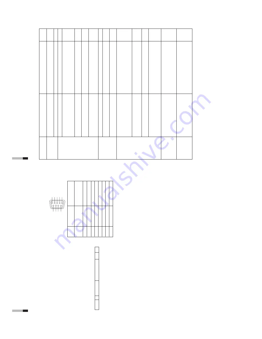
1. Cable
Prepare a straight cable with a D-sub connector (9-pin, male) and a D-sub
connector (9-pin, male)
2.
Communications Specifications
Baud Rate
:
4800/9600/19200 (factory pre-set; 4800)
Data Bits
:
8
bits
Parity
:
No parity
Stop Bits
:
1
Communication Cord :
ASCII Cord
3. Commands
Format
Header ID
Command ID Command Content Data CR
Header
!
Control from the PC to the monitor
?
Reference from the PC to the monitor
@
Answer from the monitor to the PC
ID
+
C Data
B
Basic command
Characters
00, 01 or No data
D
Command for adjusting the picture size
00 ~ 08
U, D (U: UP
, D: DOWN)
S
Command for adjusting the picture quality
00 ~ 05
U, D (U: UP
, D: DOWN)
M
Command for selecting the menu item
00 ~ 0E
00, 01, 10, 1
1
F
Command for selecting the menu item
00 ~ 10
00, 01, 02, 03, 04, 05
W
Command for adjusting the white balance
00 ~ 05
U, D (U: UP
, D: DOWN)
C
Command for inquiring for the monitor
’s
status
00
0 ~ 655
Communication Procedures
The following is the communication procedures.
1. Starting the communication
Receives the connection command (!XXBCN1Cr) from the PC
[
Sends the monitor
’s
status (@XXBOKCr) to the PC
2.
Performing the external control
Receives the control command (!XXXXCr) from the PC
[
Sends the monitor
’s
status (@XXBOKCr) to the PC
*
The monitor repeats these receiving and sending if necessary
.
3.
T
erminating the communication
Receives the termination command (!XXBCN0Cr)
[
Sends the monitor
’s
status (@XXBOKCr) to the PC
*
Hand-shake communication is used.
This means that after sending a command to the monitor
, the PC must receive a status
return from the monitor before sending the next command.
*
When the monitor is controlled by a PC via RS-485, a conversion adapter (RS-232
p
[
RS-485) is also required.
4
3
2
1
9
8
5
7
6
Pin No.
IN terminal
OUT terminal
signal
signal
1
5V Power (for
controller exclusively
NC
for this monitor)
2T
D
+
TD
+
3R
D
+
RD
+
4N
C
N
C
5N
C
N
C
6N
C
N
C
7
TD–
TD–
8
RD–
RD–
9N
C
N
C
*
The 5V power supply of the 1st terminal is for the controller
exclusively for this monitor
. Do not use it for other devices.
HOW TO USE EXTERNAL
CONTROL
(cont'd)
23
Problems
No power supply
No picture with
the power on
No sound
W
rong color
Unnatural picture
Shaking picture
Points to be checked
Is the power plug loosened or
disconnected?
Is the main power turned OFF?
Is the signal cable disconnected?
Is the power of the connected
component ON?
Is the signal output from the connected
component?
Is the input signal selected correctly?
Is the input signal adapted to the
monitor
’s
specification?
Are any of the self-check indicators
(INPUT
SELECT
A
through F buttons)
blinking?
Is the audio cable disconnected?
Is the audio signal output from the
connected component?
Is the volume output set to minimum?
Has the picture adjustment been
changed?
Has the WHITE BALANCE setting
been changed?
Are any cables connected to the
component/RGB input card?
Has the correct signal been input to the
component/RGB input card and the
correct INPUT been selected on the
monitor?
Has [CONTRAST] or [BRIGHT] been
changed?
Is the monitor close to a motor
,
transformer or any other device
generating a strong magnetic field?
(a fan, fluorescent light, laser printer
,
another monitor
, etc.)
Measures (Remedy)
Firmly insert the power plug.
T
urn the main power ON.
Connect the signal cable firmly
.
T
urn on the power of the connected component
and set it correctly
.
Select the correct input with the INPUT SELECT
buttons.
Check that the input signal format corresponds to
the installed input card format.
Follow the procedures in “SELF-CHECK
INDICA
TIONS”.
Connect the audio cable firmly
.
Set the connected component correctly
.
Adjust the speaker volume with the VOLUME
(volume adjustment) buttons.
Set each picture adjustment knob to the standard
(centered) position. Or
, set each picture
adjustment item in [ PICTURE SUB
ADJ.] in the
<SETUP MENU> screen to Standard (00) (or
use the [reset] function).
Set each [COLOR
TEMP
./BAL.] item in the
<SETUP MENU> screen to Standard (000) (or
use the [reset] function).
Connect each signal cable firmly
.
Select INPUT
A/C/E when the component signal
is input, or select INPUT B/D/F when the RGB
signal is input.
Adjust the CONTRAST or BRIGHT picture
adjustment knobs.
Or
, adjust the [CONTRAST] or [BRIGHT] item in
[PICTURE SUB
ADJ.] in the <SETUP
MENU>
screen.
Move the monitor away from the device until the
picture stops shaking.
Connect the power plug to another
AC outlet
away from the former one.
TROUBLESHOOTING
Solutions to common problems related to your monitor are described here. If none of the solutions presented here solve
the problem, unplug the monitor and consult a JVC-authorized dealer or service center for assistance.
Reference
pages
—
6
7 ~ 8
—
5
7 ~ 8
25
7 ~ 8
—
4
4, 18
18
7
7
4, 18
—


