7.5
TO GO TO A PRESET LOCATION:
Verify the LED in the “PAGE” switch in not illuminated, depress the desired preset location and the
selected camera will go to the stored pan, tilt, zoom & focus location. That particular preset LED will
illuminate when the switch is depressed.
Activating any manual control will interrupt the process of going
to a preset.
When at the preset location, the preset location LED will remain lit until another preset is
selected or any manual control is activated.
7.6
DV-180 PC COMM
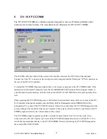
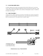
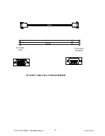
The DV-180 PC COMM is a software program that runs on the user’s personal computer. The user’s PC
must have a CD and at least one external serial port. This program performs limited camera control unit
functions and communicates with the DV-180, the DV-115, and the GY-DV300 camera via a RS-232
cable interface. The part number for the cable is 2030066; the standard length for this cable is three feet.
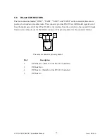
This cable is connected between the serial port on the computer and the fifteen pin “D” Sub connector on
the rear of the DV-180 Controller.
Once installed on the user’s computer the DV-180 PC COMM program provides control for the GY-
DV300 video gain, white balance, and shutter for each camera connected to the system. The program
remembers the parameters that are set using the DV-180 PC COMM. If the controller is powered off the
configuration of the camera set up is not lost. These parameters are restored for the camera when the
controller is powered back on.
7.7
TO REVERSE MANUAL CONTROL FUNCTIONS
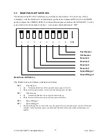
To reverse the directions of the manual functions of the DV-180 Controller use the SETUP switches
located on the rear panel of the DV-180 Controller chassis. These switches used in conjunction with the
CAMERA SELECT and the AUXILIARY 1 switches to allow reversal of the pan and tilt manual control
functions. For example, it may be necessary to reverse the direction of motion of the tilt head because the
system is being operated by a aircraft pilot. To reverse the tilt function for camera 1, perform the following
steps:
Put the SETUP Switch #7(Tilt Reverse) in the DOWN position, depress the CAMERA SELECT 1 switch
and hold it down. Depress and release the AUXILIARY 1 switch while the CAMERA SELECT 1 switch
is still depressed. Release the CAMERA SELECT 1 switch. The tilt function is now reversed for camera 1
only. To reverse the tilt function of camera 2, repeat the above procedure with the CAMERA SELECT 2
switch depressed instead of the CAMERA SELECT 1 switch. To the restore the normal polarity of the tilt
control, simply repeat the above procedure with DIP Switch #7 in the UP position.
7.8
TO SET THE SPEED RANGE
To set the speed range of the manual functions of the DV-180 Controller also use the SETUP switches
JVC DV-180 PAN/TILT Operations Manual
Doc #: D0154-A
16


