4.
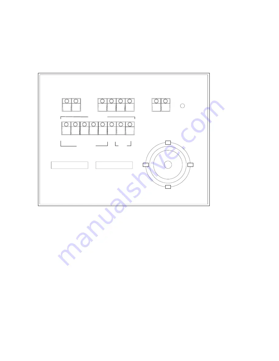
FRONT PANEL-CONTROLS AND INDICATORS.
ZOOM
FOCUS
NEAR
FAR
WIDE
TELE
DN
RT
LT
PRESET
1
2
3
4
5
6
7
8
PWR
DV-180 DIGITAL CONTROLLER
PG
PRG
1
2
3
4
CAMERA
UP
AUXILIARY
1
2
JVC
2
A/I
BARS
RECORD
ST
RC
RV
FF
PAU
A/F
OP
CL
IRIS
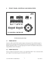
DV-180 Controller Console Front Panel
4.1
POWER SWITCH
The power switch on the DV-180 Controller is located on the lower area of the controller rear panel. To
apply power to the unit depress the bottom portion of the switch. The front panel green power LED will
illuminate indicating the power is on. Upon supplying power to the DV-180 Controller, the lamp test and
analog calibration self test will commence.
4.2
POWER INDICATOR
The power indicator for the DV-180 Controller is a green LED labeled “PWR”. This is an indication that the
power supply is connected and the power switch is in the “ON” position.
JVC DV-180 PAN/TILT Operations Manual
Doc #: D0154-A
8


