background image

4.3 

PAGE SWITCH AND INDICATOR 

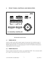
The function of the “PAGE” switch is to select preset positions one through eight, which are indicated by the 
numbers over the switches, or to select recorder, auto focus, or manual iris functions, which are indicated by 
the letters and symbols under the switches. The current page status is indicated by the illumination of the 
page LED located in the “PAGE” switch located on the upper left area of the front panel. Preset

 positions 

one through eight are 

selected if the LED is extinguished. Recorder, auto focus, or manual iris functions 

are enabled if the LED is illuminated.  

4.4 

PROGRAM SWITCH AND INDICATOR 

This switch and indicator are located adjacent to the “PAGE” switch on the upper left area of the front panel 
and can be identified by the gray switch cap. This control is used to initiate the programming of one of the 
eight presets when the “PAGE” LED is extinguished. If the “Program” LED is illuminated, depressing a 
Preset switch will program a preset to that preset number. If the “Program” LED is extinguished, the 
depression of a preset switch will send the pan & tilt head to preset location corresponding to the preset 
switch depressed. 

If the “PAGE” LED is illuminated, the “PROGRAM” switch turns the GY-DV300 Full Auto mode on or 
off. If the “PROGRAM”LED is extinguished, the Full Auto Mode is “OFF”. If the “PROGRAM” LED is 
illuminated, the Full Auto Mode is “ON”. Depressing the “PROGRAM” switch reverses the Full Auto 
Mode. 

4.5 

 CAMERA SELECT SWITCH AND INDICATOR 

These four switches and indicators are centrally located on the upper area of the front panel. The camera to 
be controlled is selected by depressing the appropriate switch. The red LED in the switch cap indicates 
which camera is selected. Note: Upon power up the controller will always default to camera number one. 

4.6 

AUXILIARY 1 SWITCH AND INDICATOR 

This switch and indicator are located on the upper right area of the front panel. As with the PRESET 
switches the AUXILLARY 1 switch performs two different functions depending on the state of the PAGE 
switch. If the LED in the PAGE switch is off, the AUX 1 switch controls the AUX 1 functions. If the LED 
in the PAGE switch is on, the AUX 1 switch controls the auto iris mode of the camera.  

The AUX1 switch is used in conjunction with the CAMERA SELECT and rear panel DIP switches to 
allow reversal of the manual control functions and to vary the speed of certain control functions. The 
functions of this switch will be discussed in depth in the operations section of this manual. 

The Camera Auto/Manual Iris mode is toggled by depressing the AUX 1 switch when the “PAGE” LED 
illuminated. The functions of this switch will also be discussed in depth in the operations section of this 
manual 

JVC DV-180 PAN/TILT Operations Manual


Doc #: D0154-A


9

Summary of Contents for DV-180

Page 1: ...OPERATIONS MANUAL for a JVC DV 180 CONTROLLER Prepared for JVC Professional Products Company 1700 Valley Road Wayne NJ 07470 Document No D0154 Date 19 November 2003 Revision A ...

Page 2: ...3 PAGE SWITCH AND INDICATOR 9 4 4 PROGRAM SWITCH AND INDICATOR 9 4 5 CAMERA SELECT SWITCH AND INDICATOR 9 4 6 AUXILIARY 1 SWITCH AND INDICATOR 9 4 7 AUXILIARY 2 SWITCH AND INDICATOR 10 4 8 PRESET SWITCHES AND INDICATORS 10 4 9 ZOOM FOCUS SEESAWS CONTROLS 10 4 10 JOYSTICK 10 5 REAR PANEL CONNECTORS AND SWITCHES 11 5 1 COMPUTER CONTROL CONNECTOR 11 5 2 CAMERA 1 4 CONNECTORS 11 5 3 GROUND SCREW 11 5 ...

Page 3: ...MANUAL CONTROL FUNCTIONS 16 7 8 TO SET THE SPEED RANGE 16 7 9 VIDEO RECORDER CONTROLS 17 7 10 AUTO FOCUS 17 7 11 MANUAL IRIS 17 7 12 AUTO IRIS 17 7 13 COLOR BAR GENERATION 18 7 14 CABLE DRAWINGS 18 8 TROUBLE SHOOTING 20 8 1 PAN TILT 20 8 2 DV 180 PC COMM 20 8 3 TECHNICAL SUPPORT 20 JVC DV 180 PAN TILT Operations Manual Doc D0154 A 3 ...

Page 4: ...tick Control of the zoom and focus is accomplished with proportional deflection Seesaw controls The proportional controls allow a slow movement when the control is only slightly depressed increasing to a faster response when the control is fully depressed In addition to basic pan tilt zoom and focus control the DV 180 allows control of iris automatic or manual video tape recording controls camera ...

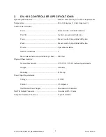
Page 5: ...Seesaw control proportional deflection Presets 8 per camera station Number of Stations 4 Max distance between controller p t head 2000 feet Physical Characteristics Size surface mount 9 75 W X 7 25 D inches sloped chassis Weight 4 Pounds Mounting Table top Power Input Requirements Voltage 12 VDC Current 0 3 Amperes Wall Mount Power Supply Provided with Controller Pan Tilt Output Connector 4 conduc...

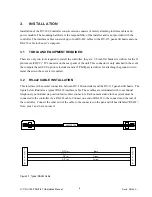
Page 6: ...d a 1 Phillips screwdriver for attaching the ground wire to metal chassis in the event it is required 3 2 RS 422 CABLE INSTALLATION This interface is the normal connection between DV 180 controllers and the DV 115 pan and tilt heads The figure below illustrates a typical RS 422 interface cable These cables are terminated with conventional telephone type modular six position four contact connectors...

Page 7: ...d by a single wall mount power module The unit requires a 12 VDC 500 ma version power module To install the power module simply plug the unit into the AC wall outlet and plug the DC plug into the jack on the rear panel of the DV 180 Controller labeled POWER 12 VDC Caution in the event the power is supplied by the user the center pin of the plug is ground DO NOT reverse the polarity 3 6 POWER ON IN...

Page 8: ...e lower area of the controller rear panel To apply power to the unit depress the bottom portion of the switch The front panel green power LED will illuminate indicating the power is on Upon supplying power to the DV 180 Controller the lamp test and analog calibration self test will commence 4 2 POWER INDICATOR The power indicator for the DV 180 Controller is a green LED labeled PWR This is an indi...

Page 9: ... extinguished the Full Auto Mode is OFF If the PROGRAM LED is illuminated the Full Auto Mode is ON Depressing the PROGRAM switch reverses the Full Auto Mode 4 5 CAMERA SELECT SWITCH AND INDICATOR These four switches and indicators are centrally located on the upper area of the front panel The camera to be controlled is selected by depressing the appropriate switch The red LED in the switch cap ind...

Page 10: ...es initiate commands to GY DV 300U video recorder The commands are stop record rewind fast forward and pause The sixth switch toggles the auto focus mode of the camera Switches seven and eight open and close the iris if the camera is in the manual iris mode 4 9 ZOOM FOCUS SEESAWS CONTROLS Located to the left of the pan and tilt joystick are the controls for zoom and focus Control of the zoom and f...

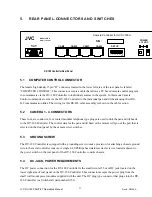
Page 11: ...ct modular telephone type plugs are used to link the pan and tilt heads to the DV 180 Controller The control data for the pan and tilt head or the camera will go out the port that is selected on the front panel by the camera select switches 5 3 GROUND SCREW The DV 180 Controller is equipped with a grounding screw to make provision for attaching a chassis ground wire to the metal controller console...

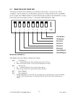
Page 12: ... Speed Range 1 Speed Range 0 REAR PANEL DIP SWITCH The Function of each of these switches is as follows SW8 Pan Reverse Up Normal pan direction left on joystick camera pans to the left Down Reverse pan direction left on joystick camera pans to the right SW7 Tilt Reverse Up Normal tilt direction up on joystick camera tilts up Down Reverse tilt direction up on joystick camera tilts down SW2 Speed Ra...

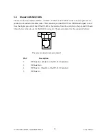
Page 13: ... The RS 422 is the interface from the controller to the pan and tilt heads Shown below is the pin out for the RS 422 connector The pin assignment for this connector follows Pin 2 Pin 5 Pin 6 Not Used Pin 1 Not Used The camera connector pin assignment Pin Description 2 P T Data Out Data In to the DV 180 Controller 3 P T Data Out 4 P T Data In Data Out of the DV 180 Controller 5 P T Data In JVC DV 1...

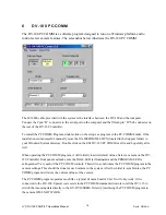
Page 14: ... 180 PC COMM exe file and hopefully all is well When operating the PC COMM program it will initially load its default values Select a camera on the DV 180 Controller front panel and make sure the PAGE LED is illuminated and the PROGRAM LED is extinguished Vary each of the PC COMM controls This will re synchronize the PC COMM program to the camera settings This should be done for each camera in the...

Page 15: ...e selected camera LED will be lit and the camera location will be under the control of the DV 180 Controller Camera 1 is the default selection at power up To position the selected pan tilt head move the joystick up down left and right To change the zoom depress the TELE or the WIDE side of the ZOOM control To change the focus depress the FAR or NEAR side of the FOCUS control 7 4 PROGRAMMING A PRES...

Page 16: ...PC COMM If the controller is powered off the configuration of the camera set up is not lost These parameters are restored for the camera when the controller is powered back on 7 7 TO REVERSE MANUAL CONTROL FUNCTIONS To reverse the directions of the manual functions of the DV 180 Controller use the SETUP switches located on the rear panel of the DV 180 Controller chassis These switches used in conj...

Page 17: ...able from the front panel of the DV 180 they are stop record rewind fast forward and pause These controls use the preset switches 1 5 To activate these controls verify the PAGE LED is illuminated indicating the functions listed under the PRESET switches are enabled and then depress desired tape command 7 10 AUTO FOCUS There is an auto focus command available from the front panel of the DV 180 This...

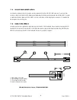
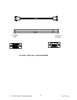
Page 18: ...two applicable cable drawings for the DV 180 Controller these include drawing 960379 the RS 422 I F cable between the DV 180 Controller and the pan and tilt heads and drawing 2030066 the RS 232 cable between the DV 180 Controller the user s personal computer 1 3 2X Pin 1 2 Blk Red Grn Yel 25 In ACA96037900 1 Strip jacket 375 Inches 2 Fan and flatten to color pattern 3 Trim straight to 250 Inches 4...

Page 19: ...203006600 BLK 2 3 5 3 2 15 15 Pin Male Plug DATA TO DV 180 GROUND YEL RED 1 2 3 4 5 7 8 9 10 6 11 12 13 14 15 DATA TO PC 1 2 3 4 5 7 8 9 6 DV 180 PC COMM CABLE P N ACA203006600 JVC DV 180 PAN TILT Operations Manual Doc D0154 A 19 ...

Page 20: ...essed Verify the interface cable is properly installed 8 2 DV 180 PC COMM Problem No CCU functions Verify correct Comm port is selected for your computer Verify configuration of 3 conductor RS 232 interface cable P N 2030066 8 3 TECHNICAL SUPPORT For technical assistance on the DV 180 call 321 956 0095 or go to web site at esi inc com Have serial number of unit and description of symptoms availabl...

Reviews: