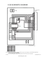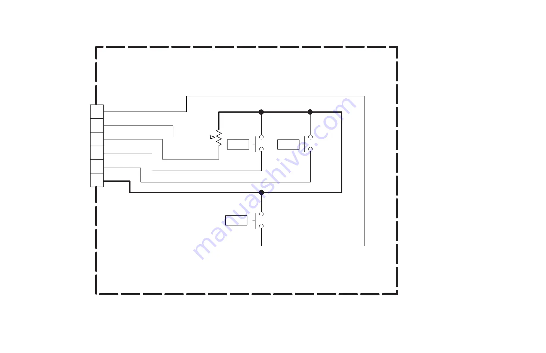
<OPE UNIT SCHEMATIC DIAGRAM>
FULL
HALF
W
T
TRIG
OPE UNIT
To MAIN
(MAIN IF)
(CN104)
ZOOM_SW
1
2
3
4
TRIG_SW
FULL_SW
5
6
GND
REG_2.83V
HALF_SW
yf335_ly10657002a_ver0.1
Replace the entire unit only.
3. The schematic diagram is only for reference. Avoid replacing individual parts.
2. Be sure to check the PARTS LIST for availability.
NOTES: 1. For the destination of each signal and further line connections that are cut off from this diagram, refer to "BOARD INTERCONNECTIONS".
created date:2010-02-19
No.YF335
(No.YF335<Rev.001>)18/30


