(No.MB353)1-15
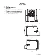
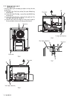
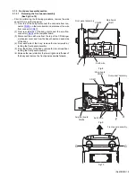
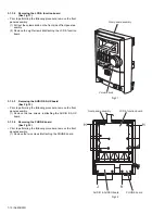
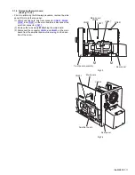
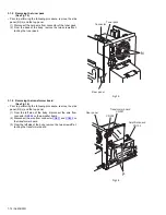
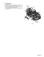
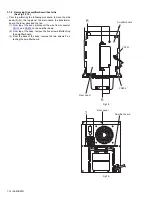
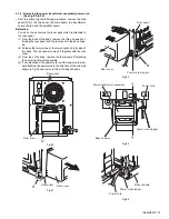
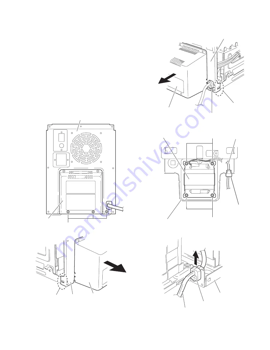
3.1.9 Removing the power transformer assembly/ power cord
(See Fig.20 to 24)
• Prior to performing the following procedure, remove the side
panel (R)/(L), the top panel, the main board, the transformer
board, the fan and the amplifier board.
Reference:
You do not need remove the tuner pack which is attached to
the rear panel.
(1) From the back of the body, remove the three screws
U
at-
taching the rear panel and the rear cover to the base chas-
sis.
(2) Release the two joints
e
at the lower right and left sides of
the body. The rear panel comes off together with the rear
cover.
(3) From top of the body, remove the four screws
Y
attaching
the power transformer assembly.
(4) If you disconnect the power cord, pull the power cord stop-
per attaching the power cord in the direction of the arrow as
shown in Fig.24 and remove it from the base chassis.
Fig.20
Fig.21
Fig.22
Fig.23
Fig.24
U
Rear panel
Rear cover
Rear panel
Rear cover
d
Rear panel
Rear cover
d
Power cord stopper
Power cord stopper
Power cord
Power transformer assembly
Y
Y
Base chassis
Base chassis
Power cord stopper
Power cord
Summary of Contents for FS-G5
Page 20: ...1 20 No MB353 SECTION 4 ADJUSTMENT This service manual does not describe ADJUSTMENT ...
Page 25: ... M E M O ...
Page 30: ...Standard schematic diagrams Front Power supply section 2 5 ...
Page 32: ...Main section 2 7 ...
Page 33: ...2 8 ...
Page 34: ...Amp section 2 9 ...
Page 35: ...2 10 ...
Page 36: ...CD section 2 11 ...
Page 37: ...2 12 ...
Page 39: ... Cu melting point 219 Centigrade 2 14 ...
Page 41: ...ng point 219 Centigrade 2 16 ...
Page 43: ...solder used in the board material Sn Ag Cu melting point 219 Centigrade 2 18 ...
Page 45: ...in the board material Sn Ag Cu melting point 219 Centigrade 2 20 ...
Page 49: ... M E M O ...


