(No.MB353)1-7
SECTION 3
DISASSEMBLY
3.1
Main body
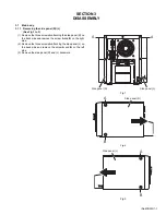
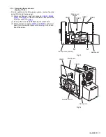
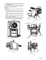
3.1.1 Removing the side panel (R)/ (L)
(See Fig.1 to 3)
(1) Remove the three screws
A
attaching the side panel (R) on
the back side and remove the screw
A
and
B
on the right
side.
(2) Remove the three screws
A
attaching the side panel (L) on
the back side and remove the screw
A
and
B
on the left
side.
(3) Remove the side panel (R) and (L) backward.
Fig.1
Fig.2
Fig.3
A
A
Side panel (R)
Side panel (L)
A
B
Side panel (R)
A
B
Side panel (L)
Summary of Contents for FS-G5
Page 20: ...1 20 No MB353 SECTION 4 ADJUSTMENT This service manual does not describe ADJUSTMENT ...
Page 25: ... M E M O ...
Page 30: ...Standard schematic diagrams Front Power supply section 2 5 ...
Page 32: ...Main section 2 7 ...
Page 33: ...2 8 ...
Page 34: ...Amp section 2 9 ...
Page 35: ...2 10 ...
Page 36: ...CD section 2 11 ...
Page 37: ...2 12 ...
Page 39: ... Cu melting point 219 Centigrade 2 14 ...
Page 41: ...ng point 219 Centigrade 2 16 ...
Page 43: ...solder used in the board material Sn Ag Cu melting point 219 Centigrade 2 18 ...
Page 45: ...in the board material Sn Ag Cu melting point 219 Centigrade 2 20 ...
Page 49: ... M E M O ...


