background image

1-18 (No.YF075)

SECTION 5

TROUBLE SHOOTING

5.1

SERVICE NOTE

Sy

m

b

o

l No

.

R

e

m

o

ving order of screw

Place to stick screw

R

eference drawing (Fig.No.)

Screw tightening torque

Sy

m

b

o

l No

.

R

e

m

o

ving order of screw

Place to stick screw

R

eference drawing (Fig.No.)

Screw tightening torque

R

e

m

o

ving order of screw

Place to stick screw

R

eference drawing (Fig.No.)

Screw tightening torque

R

e

m

o

ving order of screw

Place to stick screw

R

eference drawing (Fig.No.)

Screw tightening torque

[1]

FA1

FA2

FA3

FA4

FA5-2

FA5-1

123456789

1

0

1

1

1

2

1

3

1

4

1

5

1

6

12345

17

㧖㧖

㧖㧖

㧖㧖

[2]

[5]

[6]

[3]

[4]

CABINET PARTS AND ELECTRICAL PARTS(1)

12

123456789

1

0

1

1

3-2-3-2

VF1

3-2-3-3

3-2-3-1

[2]

[2] 

MONITOR ASSY

[3] 

[3] 

VF ASSY

123456789

1

0

1

1

3-2-4

[7] 

[7] O

P BLOCK ASSY / CCD BOARD ASSY

NOTE:

㧝㧖

 (This mark shows where to attach the screws) : Do not reuse the screws because the screw lock bond was applied to prevent the 

screws from loosening. 


Prepare the specified screws and use them in place of the removed screws.

Tightening torque for the screws

There are setting limits of the torque value for the torque driver. If the value exceeds the setting value, take it as a rough 

measurement (reference value),  


and tighten the screw manually. 

The specified torque value is a recommended value of the initial assembly. Therefore, set the value below the specified torque 

value in the assembling procedure.


Be careful not to break either the screws or the screw holes.

ޓ

a

 0.092N

m (0.94kgf

cm

)

ޓޓ

b

 0.078N

m (0.8kgf

cm) 

ޓޓ

c

 0.069N

m (0.7kgf

cm)

ޓޓ

d

 0.098N

m

 (1.0kgf

cm)

ޓޓG㧦

 0.118N

m (1.2kgf

cm)

aa

d

c

e

b

FA5-1

FA6

[9]

[10]

[11]

[12]

21

22

23

24

25

26

28

27

㧖㧖㧖㧖㧖㧖㧖

㧖㧖

[7]

[8]

FA7

FA8

CABINET PARTS AND ELECTRICAL PARTS(2)

ab

c

a

18

19

20

-

-

-

-

-

-

-

-

-

Summary of Contents for GR-D270US

Page 1: ...R D275US GR D290US GR D295US For disassembling and assembling of MECHANISM ASSEMBLY refer to the SERVICE MANUAL No 86700 MECHANISM ASSEMBLY TABLE OF CONTENTS 1 PRECAUTIONS 1 3 2 SPECIFIC SERVICE INSTRUCTIONS 1 5 3 DISASSEMBLY 1 6 4 ADJUSTMENT 1 15 5 TROUBLE SHOOTING 1 18 GR D270US GR D271US GR D275US M5D2S5 GR D290US GR D295US M5D2S7 ...

Page 2: ...mm 25 1 power zoom lens Filter diameter Ø27 mm LCD monitor 2 5 diagonally measured LCD panel TFT active matrix system Viewfinder Electronic viewfinder with 0 16 color LCD Speaker Monaural LED Light Effective distance 1 5 m 5 ft For Digital Video Camera Format DV format SD mode Signal format NTSC standard Recording Playback format Video Digital component recording Audio PCM digital recording 32 kHz...

Page 3: ...rts 9 When a power cord has been replaced check that 10 15 kg of force in any direction will not loosen it Fig 1 1 2 10 Also check areas surrounding repaired locations 11 Products using cathode ray tubes CRTs In regard to such products the cathode ray tubes themselves the high voltage circuits and related circuits are specified for compliance with recognized codes pertaining to X ray emission Cons...

Page 4: ...g prongs and externally exposed accessible parts Use an AC voltmeter to measure across both terminals of load Z See Fig 1 1 9 and following Fig 1 1 12 Fig 1 1 9 5 Grounding Class 1 model only Confirm specified or lower grounding impedance between earth pin in AC inlet and externally exposed accessible parts Video in Video out Audio in Audio out or Fixing screw etc Measuring Method Connect milli oh...

Page 5: ... following table indicate main different points between models GR D270US GR D271US GR D275US GR D290US and GR D295US MODEL GR D270US GR D271US GR D275US GR D290US GR D295US DSC FLASH MEMORY MEMORY CARD NO NO NO MMC 8MB NO REMOTE CONTROL NO RM V720US RM V720US RM V720US RM V720US ...

Page 6: ...nism tape transport system optical lens surface 3 2 ASSEMBLY AND DISASSEMBLY OF MAIN PARTS 3 2 1 Assembly and disassembly When reassembling perform the step s in reverse order 1 Order of steps in Procedure When reassembling preform the step s in the reverseorder These numbers are also used as the identification location No of parts Figures 2 Part to be removed or installed 3 Fig No showing Procedu...

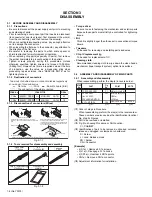
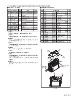
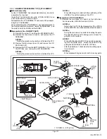
Page 7: ...Y MAIN BOARD ASSY FRAME Z27 ASSY SIELD COVER PR PRE MDA BOARD ASSY MECHA B ASSY GRIP BELT S1a S1b S1c L1a b c d e f S2a 5 S2b CASSETTE COVER S2c S2d L2 CN2 2 S3a 2 S3b L3 CN3 S4a S4b L4a b CN4a b L5a b CN5a b S6 L6a b c CN6a b 2 S6b PLATE MIC MIC L6e d FRONT BOARD ASSY CN7a CN7b S8 L8a b CN8a b 3 S9 2 S10 L10 CN11a b c d e f 2 S11 FA1 FA2 FA3 FA4 FA5 1 2 FA6 FA7 FA8 NOTE1a b NOTE2a b NOTE4a b c NO...

Page 8: ...SY 11 S2d 5 S2b 6 S2b 7 S2b 8 S2b 9 S2b BOTTOM VIEW L2 NOTE2a 4 S2a BOTTOM VIEW 4 3 a CN3 CN3 CN4a CN4a CN4b NOTE4a NOTE4a NOTE4b NOTE4c CN4b 12 S3a 13 S3a 17 S4 15 S3b 14 S3b 16 S4 b c b a c 12 16 L4a REAR UNIT REAR UNIT L3 L3 EJECT SW L4b 5 CN5a CN5b L5a L5a 7 a a 6 CN6b CN6a CN7a CN7b 18 S6 L6a L6b L6c ...

Page 9: ...SY FRONT COVER ASSY PLATE MIC 19 S6b 20 S6b L6e L6d 21 S8 CN8b CN8a 8 L8a L8b FPC SHIELD COVER PR 10 24 S9 22 S9 23 S9 26 S10 25 S10 9 㧦 0 078N㨯m 0 8kgf㨯cm 㧦 0 069N㨯m 0 7kgf㨯cm L10 NOTE10 a b c d e f 12 11 28 S11 27 S11 CN11b CN11c CN11d CN11f CN11e CN11a a b c d e f ...

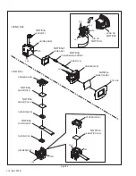
Page 10: ...two screws 5 and 6 and remove the COV ER HINGE 5 Remove the two screws 7 and 8 and remove the MON ITOR ASSEMBLY NOTE2b When removing be careful not to damage the FPC ASSEMBLY zDisassembly of MONITOR ASSEMBLY 1 Remove the three screws 9 11 and remove the MON ITOR COVER ASSEMBLY by disengaging the five hooks L2c d e f and g 2 Pull out the U D SWITCH BOARD from the MONITOR CASE ASSEMBLY 3 Release the...

Page 11: ...SE ASSY 8 S2c 7 S2c 9 S2d 10 S2d 11 S2d 12 S2d b c b b CN2b CN2c d c MONITOR CASE ASSY MONITOR COVER ASSY MONITOR BOARD ASSY BACKLIGHT ASSY SPACER LCD LCD MODULE SHIELD CASE DIFF SHEET should put this part at right side MONI HINGE ASSY U D SW d a b BOTTOM VIEW SPRING LCD a b b NOTE2b SD2 SD2 㧦 0 98N㨯m 1 0kgf㨯cm ...

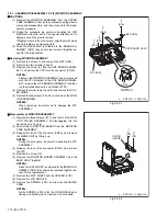
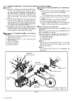
Page 12: ...e OP LPF zAssembly of CCD BASE ASSEMBLY and CCD BOARD AS SEMBLY 1 Set the OP LPF to the OP BLOCK ASSEMBLY so that the OP side touches the OP BLOCK ASSEMBLY NOTE7a Pay careful attention to the orientation of the OP LPF 2 Set the SHEET to the OP LPF not to come off the right position 3 Attach the SPACER to the OP BLOCK ASSEMBLY 4 Fasten them together with the two screws 1 2 5 Set the CCD BOARD ASSEM...

Page 13: ...he procedure be careful not to break the FPC NOTE3c When attaching be careful with the positioning of the LEVER VF and the handling of the FPC zDisassembly of LCD SA LENS SA 1 Remove the two hooks L3c and d on the both sides and remove the LENS SA from the LCD SA NOTE3d Refer to the Fig VF2 for the disassembly of the LCD SA and the LENS SA do not disassemble unless it is needed NOTE3e During the p...

Page 14: ...LDER LCD GUIDE LCD LCD MODULE CUSHION LCD SHEET POLA 1 SHEET DIFF CASE B LIGHT LEVER VF GUIDE LENS LENS ASSY COMPRESION SPRING SHAFT VF HOLDER EYE SHEET LENS EYE CUP LENS SA LCD SA NOTE3e NOTE3e f NOTE3g NOTE3e NOTE3e NOTE3e NOTE3e NOTE3e L3g L3h L3j L3m L3k L3p L3n LCD SA LENS SA ...

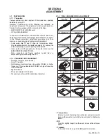
Page 15: ...PC 4 1 2 REQUIRED TEST EQUIPMENT Personal computer for Windows Color TV monitor Oscilloscope dual trace type observable 100MHz or higher frequency The one observable 300 MHz or higher frequency is recommended Digital voltmeter DC power supply or AC adapter Frequency counter with threshold level adjuster 4 1 3 TOOLS REQUIRED FOR ADJUSTMENT Torque driver Be sure to use to fastening the mechanism and...

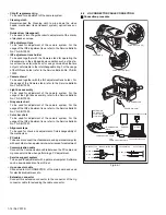
Page 16: ...For the usage of the INF adjustment lens refer to the Service Bulletin No YA SB 10035 Color bar chart To be used for adjustment of the camera system For the usage of the INF adjustment lens refer to the Service Bulletin No YA SB 10035 Alignment tape To be used for check and adjustment of interchangeability of the mechanism PC cable To be used to connect the Videocamera and a personal computer with...

Page 17: ...RICAL ADJUSTMENT Electrical adjustment is performed by using a personal computer and software for SERVICE SUPPORT SYSTEM Read README TXT file to use the software properly As for the connection of cables see 4 2 JIG CONNECTOR CABLE CONNECTION 21 22 23 24 25 26 27 28 29 30 31 32 33 34 35 36 37 38 39 40 EXMOD_1 SYS_TMS SYS_TCK SYS_TDI SYS_TRSTL SYS_TDO SYS_RSTL AL_3VSYS IF_TX JLIP_TX JLIP_RX TXD2 RXD...

Page 18: ...CD BOARD ASSY NOTE 㧝 㧖 This mark shows where to attach the screws Do not reuse the screws because the screw lock bond was applied to prevent the screws from loosening Prepare the specified screws and use them in place of the removed screws 㧞 Tightening torque for the screws There are setting limits of the torque value for the torque driver If the value exceeds the setting value take it as a rough ...

Page 19: ...ell 2 Though the idler gear and reel disk are engaged with each other the tape is not wound because of overload to the mechanism 3 No FG pulse is output from the reel sensor 4 No power is supplied to the reel sensor 5 Tape transport operation takes place with a cassette having no tape inside 6 The tape slackens and no pulse is produced until the slack is taken up and the tape comes into the normal...

Page 20: ... No YF075 AV MULTIMEDIA COMPANY CAMCORDER CATEGORY 12 3 chome Moriya cho kanagawa ku Yokohama kanagawa prefecture 221 8528 Japan Victor Company of Japan Limited VPT Printed in Japan ...

Reviews: