(No.YF087)1-19
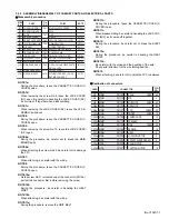
Jig connector diagrams
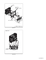
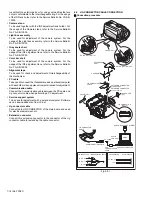
Fig.4-2-2
4.3
MECHANISM COMPATIBILITY ADJUSTMENT
4.3.1 Tape pattern adjustment
NOTE:
Prior to the adjustment, remove the COVER (ADJ).
(1) Play back the compatibility adjustment tape.
(2) While triggering the HID, observe the waveform of
ENV_OUT.
(3) Set the manual tracking mode (ATF OFF).
(4) Confirm that the waveform is entirely parallel and straight,
and free from remarkable level-down, through the tracking
operation.
Make the confirmation as follows if necessary.
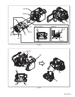
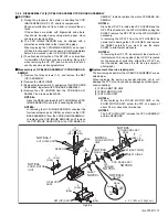
(5) If level-down is observed on the left hand side of the
waveform, straighten the level by turning the GUIDE
ROLLER (SUP).
If level-down is observed on the right hand side of the
waveform, straighten the
level by turning the GUIDE ROLLER (TU).
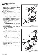
For actual adjustment, first, turn both the GUIDE ROLL-
ERS (SUP and TU) to tightening direction (clockwise) in or-
der to misalign the waveform once.
Next, turn the GUIDE ROLLERS to returning direction
(counterclockwise), then stop turning at the point where the
waveform becomes flat.
Turn only the GUIDE ROLLER (SUP) further more, then
stop turning at the point where the waveform starts chang-
ing.
(6) After the adjustment, try the unloading motion once, and
confirm that the waveform is flat when the tape has been
played back again.
(7) Play back the self-recording.
(8) Confirm that the waveform is flat.
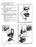
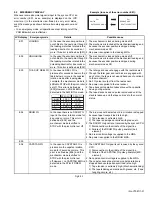
Fig.4-3-1
Fig.4-3-2
4.4
ELECTRICAL ADJUSTMENT
Electrical adjustment is performed by using a personal computer
and software for SERVICE SUPPORT SYSTEM. Read
README.TXT file to use the software properly.
As for the connection of cables, see "4.2 JIG CONNECTOR
CABLE CONNECTION".
NOTE:
The JIG connector board uses
30 pins from among 40 pins of
CN113 on the MAIN board.
Pins 1 to 5, 21 to 24 and 34 of
CN113 on the MAIN board are
not used
21
22
23
24
25
26
27
28
29
30
31
32
33
34
35
36
37
38
39
40
EXMOD_1
SYS_TMS
SYS_TCK
SYS_TDI
SYS_TRSTL
SYS_TDO
SYS_RSTL
AL_3VSYS
IF_TX
JLIP_TX
JLIP_RX
TXD2
RXD2
NC
I_MTR
NC
NC
ENV_OUT
MAIN_VCO
ATFI
HID
DISCRI
FS_PLL
HST
MON_B
NC
MON_G
GND
GND
V_OUT
NC
CVF_B
CVF_R
CVF_G
GND
NC
NC
DSC_DBG
KENTO
MVD
1
2
3
4
5
6
7
8
9
10
11
12
13
14
15
16
17
18
19
20
JIG CONNECTOR CABLE (YTU93106C)
MAIN CN113
JIG CONN. BOARD
(PIN NO.)
JLIP_RX
RXD2
I_MTR
NC
MAIN_VCO
HID
FS_PLL
MON_B
MON_G
GND
NC
CVF_R
GND
NC
KENTO
JLIP_TX
TXD2
NC
NC
ENV_OUT
ATFI
DISCRI
HST
NC
V_OUT
CVF_B
CVF_G
NC
DSC_DBG
MVD
6
7
8
9
10
11
12
13
14
15
16
17
18
19
20
25
26
27
28
29
30
31
32
33
35
36
37
38
39
40
ENV_OUT
HID
Flatten the waveform.
Misalignment of guide roller
height on the take-up side
Misalignment of guide
roller height on the
supply side


