background image

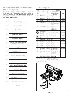
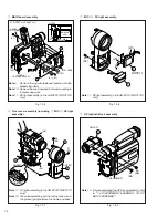
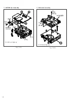
1-12

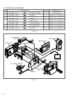
1.6

DISASSEMBLY/ASSEMBLY OF ELECTRONIC
 VIEWFINDER (VF)

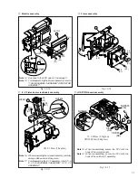
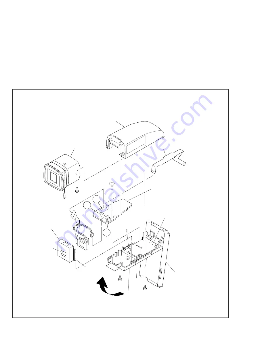
1.6.1   Disassembly/Assembly of B/W VF

Note

 1: When remove the B/W VF, leave the hinge assem-

bly VF), bracket (VF) and VF case (L) as they are
fitted to the VF. For remove the hinge assembly (VF)
and bracket (VF), refer to the exploded view (section
5).

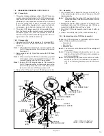
1. Raising the VF assembly, remove two screws (1, 2) and

then remove the eye piece assembly.

2. Remove two screws (3, 4) and then remove the VF case

assembly (U) while unhooking it from L1 and L2.

Fig. 1-6-1

Note

 2: When assembling, move the FPC inwards with a wire

paying careful attention to it not to break it.

3. Pull the wire out of the connector V.
4. Unlocking the connector W, pull out the FPC.
5. While holding the holder (LCD) by hand, remove the LCD

module together with the backlight.

Note 

3: When assembling, set the bosses (L3, L4) of the

holder (LCD) in the groove.

6. Remove one screw (5) and then remove the VF (B/W)

board assembly.

HINGE  ASSY(VF)

VF  CASE(L)

VF  CASE(U)

EYE  PIECE  ASSY

1

(S20)

(L4)

(L3)

(L2)

BRACKET(VF)

FPC

HOLDER(LCD)

B/W  VF  BOARD

ASSY

4

(S20)

3

(S20)

2

(S20)

5

(S21)

W

X

V

(L1)

 : 0.07N·m (0.7kgf·cm)
Summary of Contents for GR-DVF11U

Page 1: ...ctronic viewfinder with 0 55 color LCD Speaker Monaural Operating temperature 0 C to 40 C 32 F to 104 F Operating humidity 35 to 80 Storage temperature 20 C to 50 C 4 F to 122 F Dimensions 188 W x 118 H x 88 D mm 7 7 16 x 4 11 16 x 3 1 2 with the LCD monitor closed and the viewfinder pushed down Weight Approx 700 g 1 6 lbs Connectors S Video Y 1 Vp p 75 Ω analog output C 0 29 Vp p 75 Ω analog outp...

Page 2: ...NLY 3 1 3 3 SETUP 3 1 3 4 ELECTRONIC VIEWFINDER E VF ADJUSTMENT 3 3 3 4 1 Black level 3 3 3 4 2 Gain 3 3 3 5 FUSE LOCATION FOR MAIN 3 4 4 CHARTS AND DIAGRAMS NOTES OF SCHEMATIC DIAGRAM 4 1 CIRCUIT BOARD NOTES 4 2 4 1 BOARD INTERCONNECTIONS 4 3 4 2 JACK AND VF IF SCHEMATIC DIAGRAMS 4 5 4 3 SYSCON SCHEMATIC DIAGRAM 4 7 4 4 DECK CPU SCHEMATIC DIAGRAM 4 9 4 5 DV DSP SCHEMATIC DIAGRAM 4 11 4 6 DV EQ SC...

Page 3: ...nce with recognized codes pertaining to X ray emission Consequently when servicing these products replace the cath ode ray tubes and other parts with only the specified parts Under no circumstances attempt to modify these circuits Unauthorized modification can increase the high voltage value and cause X ray emission from the cathode ray tube 12 Crimp type wire connector In such cases as when repla...

Page 4: ...eter to measure across both terminals of load Z See figure 9 and following table 2 5 Grounding Class 1 model only Confirm specified or lower grounding impedance between earth pin in AC inlet and externally exposed accessible parts Video in Video out Audio in Audio out or Fixing screw etc Measuring Method Connect milli ohm meter between earth pin in AC inlet and exposed accessible parts See figure ...

Page 5: ...diagram 4 Indicates parts and points such as screws washers springs which must be removed during disassembly assembly P Spring W Washer S Screw Lock L soldering SD shield connector etc Example Remove W1 Washer W1 Remove SD1 Soldering at the point SD1 Connector A Disconnector the connector A 5 Precautions on disassembly assembly SECTION 1 DISASSEMBLY 1 1 BEFORE ASSEMBLY AND DISASSEMBLY 1 1 1 Precau...

Page 6: ...mbly Note Screw that are asterisked marked with in the shape column are fixed with screw lock agent If such the screw in once removed never used it again Table 1 1 1 SHAPE COLOR PARTS NO S1 S2 S3 S4 S5 S6 S7 S8 S9 S10 S11 S12 S13 S14 S15 S16 S17 S18 S19 SYMBOL LY30019 014A QYSLSF2090D LY30018 044A YQ43762 5 QYSLSF2055D BLACK BLACK BLACK BLACK GOLD GOLD GOLD SILVER BLACK GOLD QYSLSP2030D BLACK QYSP...

Page 7: ...or for using commodities that are not yet conformable to the interchangeable ring 17 CLEANING CLOTH KSMM 01 15 16 SOLDERING KIT YTU96016B 18 PC CABLE QAM0099 002 SERVICE SUPPORT SYSTEM YTU94057 41 11 Light box To be used for adjustment of the camera system 12 Camera stand To be used together with the INF adjustment lens holder 13 Patch cord To be used to connect electrical parts P C boards etc for...

Page 8: ...D COVER CN P Q R MECHANISM ASSY Fig 1 3 15 2 S10 HOLDER 1 3 DISASSEMBLY ASSEMBLY OF CABINET PARTS 1 3 1 Disassembly flow chart This flowchart indicates the disassembly step for the cabi net parts and board assembly in order to gain access to item s to be serviced When reassembling perform the step s in reverse order Bend route and dress the flat ca bles as they were originally 1 3 2 Disassembly me...

Page 9: ...tling pay heed to the hook L4 not to damage it Note 4 When drawing the top cover out of the E VF assembly spread the frame slightly outwards with care not to damage any part Note 5 Remove the CAP HOOD before proceeding to the removing work Note 6 Remove the cap RCA before proceeding to the removing work Note 7 Be careful not to damage the FPCandconnectorbecausethe FPC is internally connected Note ...

Page 10: ... with the bracket monitor Note 10 Remove the cap rear jack before proceeding to the removing work Note 11 DC light assembly in the GR DVF21U DVF31U only 21 S1 22 S5 L8 8 6 7 L9 NOTE12 WIRE MIC NOTE11 J 23 S1 L10 L11 8 7 NOTE 11 9 25 S6 24 S6 CUSHION OP NOTE 13 Note 13 For disassembling the OP block Assembly refer to 1 4 DISASSEMBLY ASSEMBLY OF OP BLOCK ASSEMBLY Note 11 DC light assembly in the GR ...

Page 11: ...0 15N m 1 5kgf cm 0 07N m 0 7kgf cm 0 05N m 0 5kgf cm NOTE15 28 S1 26 S1 27 S1 L1 10 NOTE14 FPC ASSY FRAME ASSY L12 NOTE18 L13 NOTE19 O 13 L O M N 36 S8 37 S9 Note 18 When reassembling secure the FPC with the hook of the motor bracket Note 19 When reassembling secure the FPC with the hook of the catcher T assembly 12 K 33 S1 32 S1 35 S1 34 S1 L3 Note 16 Whenreinstallingthemonitorassembly carefully...

Page 12: ...1 8 Fig 1 3 14 Fig 1 3 15 SECOND board assembly Mechanism assembly 0 07N m 0 7kgf cm SHIELD COVER 14 P Q R 38 S8 L14 L15 L16 L17 15 HOLDER 40 S10 39 S10 0 07N m 0 7kgf cm ...

Page 13: ... assem bly and mount a new CCD image sensor on it 4 Remove the CCD spacer optical LPF and spacer rubber 1 4 3 Assembly 1 As the optical LPF is fitted with the spacer rubber set it in the holder located in the center of the lens of the OP block assembly Note 4 When mounting the optical LPF pay heed to its ori entation because it has different surfaces in the front and back sides 2 Making sure that ...

Page 14: ...he FPC While unhooking two hooks L9 L10 remove the MONITOR board assembly Note 5 When remounting the MONITOR board assembly carefully arrange the FPC and wires Note 6 In case of the 3 inch monitor fold down the FPC on the connector U 5 After unhooking seven hooks L11 to L17 in the numeri cal order remove the holder PWB Note 7 When remounting the holder PWB arrange the backlight wires inside the ho...

Page 15: ...15 L4 NOTE7 HINGE COVER U NOTE2 NOTE2 NOTE2 NOTE3 9 LCD MODULE HOLDER LCD NOTE8 BRACKET EARTH BRACKET MONITOR CASE ASSY BRACKET a a c b b c f g f g d d e e T S 10 S19 8 S18 9 S19 0 07N m 0 7Kgf cm 0 1N m 1 0Kgf cm L6 L3 L1 L2 L5 L14 L10 L15 L13 L9 L17 L12 FPC FPC WIRE L18 L19 L8 L7 L11 L16 NOTE7 L20 L21 U NOTE6 HOLDER PWB Fig 1 5 1 ...

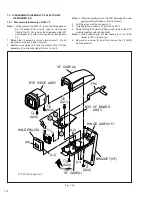
Page 16: ...se assembly U while unhooking it from L1 and L2 Fig 1 6 1 Note 2 When assembling move the FPC inwards with a wire paying careful attention to it not to break it 3 Pull the wire out of the connector V 4 Unlocking the connector W pull out the FPC 5 While holding the holder LCD by hand remove the LCD module together with the backlight Note 3 When assembling set the bosses L3 L4 of the holder LCD in t...

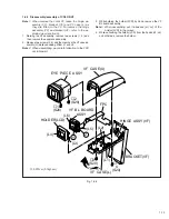
Page 17: ...s 3 4 and then remove the VF case as sembly U while unhooking it from L1 and L2 Note 2 When assembling pay careful attention to the FPC not to break it Fig 1 6 2 3 While holding the holder LCD by hand remove the VF BL board assembly Note 3 When assembling set the bosses L3 L4 of the holder LCD in the groove 4 While unhooking the holder LCD from the hooks L5 L6 on both sides remove the holder HINGE...

Page 18: ...1 14 1 7 CONNECTION OF CONNECTORS Fig 1 7 1 ...

Page 19: ...housing is accordingly lifted up If this Fig 1 8 1 SUP REEL DISK 2 3 1 4 TU REEL DISK CAPSTAN MOTOR DRUM LOADING MOTOR DC3V MONITOR ASSY operation takes place the part of the tape remaining out side is caught in the cassette lid and the tape may be damaged partially Be careful not to supply the DC power excessively 5 Turn the center gear with a sharp pointed stick chip IC replacing jig etc in the ...

Page 20: ... YTU94074 10 MAIN PWB CN104 VF COLOR CN7301 20 YTU94077 20 YTU94074 20 5 MAIN PWB CN110 OPE COVER UNIT 10 YTU94077 10 YTU94074 10 6 MAIN PWB CN109 ZOOM UNIT 15 YTU94077 15 YTU94074 15 1 9 EXTENTION CABLE CONNECTION Fig 1 9 1 No Connected point Pin No Note Patch cord Table 1 9 1 4 3 2 5 6 1 TV MONITOR LOWER CASE ASSY MAIN 01 AC POWER ADAPTER MONITOR ASSY FRONT ASSY FRAME ASSY OP BLOCK ASSY VF COLOR...

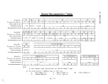
Page 21: ...1 17 1 10 SERVICE NOTE Fig 1 10 1 Screw Management Table ...

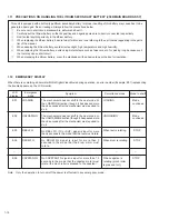
Page 22: ...perature and high humidity 6 When replacing the lithium battery avoid using metallic tools such as tweezers etc for picking it up because such the tool may cause shortcircuit 7 When disposing the lithium battery cover the electrodes with adhesive tape or the like for insulation 1 11 PRECAUTIONS ON HANDLING THE LITHIUM SECONDARY BATTERY J506 MAIN BOARD ASSY Emergency mode Symptom Survellance mode M...

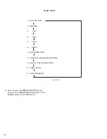
Page 23: ...ay 2 Fig 1 13 1 5 Turn the MENU BRIGHT Dial in the direction of the arrow to set the cursor at ON Then press the MENU BRIGHT Dial once The fifth page of the DISPLAY appears on the LCD monitor or in the viewfinder DEMOMODE isswitched ON from OFF status 6 Press the SELECT DIAL once The camcorder automatically enters the DEMONSTRATION mode and it repeats demonstra tion operation While the camcorder i...

Page 24: ... 5 1 250 6 SEPIA 7 B W MONOTONE 8 TWILIGHT with WHITE BALANCE 9 SLOW 4X SLOW SHUTTER 10 VIDEO ECHO 11 AUTO RELEASE Flow chart Fig 1 13 2 2 How to cancel the DEMONSTRATION mode To cancel the DEMONSTRATION mode turn the POWER switch off POWER OFF ...

Page 25: ...ts When reassembling follow these numbers in the reverse order Circled numbers in this column correspond to those appearing in drawings of this section 2 This column shows part names corresponding to circled numbers in the left column 3 The symbol T or B appearing in this column shows the side which the objective part is mounted on T the upper side B the lower side 4 Symbols appearing in this colu...

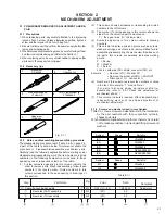
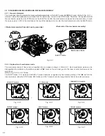
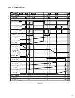
Page 26: ...te housing assembly Back side of the mechanism assembly Motor DC3V EJECT mode Back side of deck Fig 2 2 1 2 2 2 Explanation of mechanism mode The mechanism mode of this model is classified into six modes as shown in Table 2 2 1 Each mechanism mode can be distinguished from others by the relative position of v mark on the sub cam gear to the inner or outer protrusion on the main deck Refer to Fig 2...

Page 27: ... DECK 3 2 1 RELEASE GUIDE SUP LOADING SUB BRAKE T PINCH ROLLER BRAKE PAD ARM TENSION 0 0 0 EJECT C IN 30 31 7 33 70 74 04 77 SHORT FF STOP 169 2 160 176 REV 211 5 200 220 PLAY 280 3 265 291 5 43 1 45 6 47 4 46 8 49 5 51 5 122 5 129 5 134 7 156 6 148 1 162 9 44 6 47 2 49 1 49 2 52 0 54 1 161 7 155 5 147 0 250 5 265 0 275 6 SLIDE START SLIDE END Table 2 2 1 ...

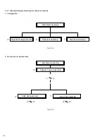
Page 28: ...deck assembly Mechanism assembly Main deck assembly Slide deck assembly Cassette housing assembly Cassette housing assembly 1 B C A B C Fig 2 2 8 Fig 2 2 9 2 2 4 Disassembling reassembling mechanism assembly 1 Configuration 2 Procedures for disassembly ...

Page 29: ...lide guide plate assembly T M7 S3 21 Adjustment Collar T M7 11 Collar T M7 11 Sub brake assembly T M7 W1 L13 P6 20 q Control plate assembly T M7 2 W1 L14 P7 20 C Main deck assembly w Tension lever assembly T M8 19 e Slide lever assembly T M8 18 r Brake control lever assembly T M8 17 t Loading guide T M9 S2 y Timing belt T M9 16 u Center gear assembly T M9 i Motor bracket assembly T M9 2 S2 12 o Wo...

Page 30: ... 17 18 27 6 5 21 2 30 22 33 29 13 28 12 11 9 10 37 36 CMain deck assembly BSlide deck assembly 35 7 25 3 8 26 24 19 20 Fig 2 2 10 Top view Fig 2 2 11 Bottom view 32 23 38 39 40 31 CMain deck assembly BSlide deck assembly ...

Page 31: ...re that there is no deformation in the frame or no damage to the switches etc Note 30 After reassembling the component parts check the mechanism operation in the PLAY mode For details of checking method refer to 2 2 8 Reassembling slide deck assembly and main deck assembly STOP mode EJECT mode PLAY mode Note 2 When removing the reel disk assembly be careful not to break the brake pad which applies...

Page 32: ...bly to the mechanism as the pad arm assembly is moved to the extent in the direction of the arrow Fig M4 4 9 Cleaner arm assembly 0 Slant pole arm assembly Drum assembly Note 5 When removing the cleaner arm assembly it is recommended to remove the slant pole arm assembly together with it except the case of a single unit replacement because the hook L5 is hard to disengage Note 6 When the shield is...

Page 33: ... set in the arm groove Fig M6 6 B Slide deck assembly C Main deck assembly Note 10 When removing the slide deck assembly pay heed to the three components of the following because they are apt to come off after the slide deck assembly is removed w Tension lever assembly e Slide lever assembly r Brake control lever assembly For reassembling those components refer to Fig M8 on page 2 10 Note 24 When ...

Page 34: ...details of reassembling procedure refer to 2 2 8 Reassembling slide deck assembly and main deck as sembly on page 2 15 Note 22 The pad arm assembly controls the tension level of the ten sion arm assembly For adjustment of the tension arm as sembly refer to page 2 8 Note 23 When reinstalling the load brake assembly slightly lift the slide deck assembly upwards because the lower part of the load bra...

Page 35: ...ar W Brake control plate E Rotary encoder R Connect gear T Reel drive pulley assembly Note 13 When removing refitting parts pay careful attention to the flexible board and so on not to damage them Note 15 When reinstalling the main cam gear and the brake control plate first fit them together so that the protrusion on the brake control plate is set in the slot on the main cam gear as shown below ne...

Page 36: ...S2 19 S2 18 S2 W1 23 S2 39 38 37 36 Fig M11 11 Y Catcher T assembly U Capstan motor I Charge arm assembly O Sub cam gear P PWB holder Note 14 The following figure shows how to put the charge arm assem bly and sub cam gear assembly together ...

Page 37: ... 27 W1 P7 P4 P5 W1 W1 W1 W1 W1 W1 W1 P6 P1 P2 20 S2 21 S2 7 S2 15 S2 16 S2 12 S2 22 S2 24 S2 6 S1 5 S1 4 S2 11 S3 10 S2 23 S2 7 S2 8 S2 13 S2 Cassette housing assembly CMain deck assembly 1 S1 L2 L4 L3 L1 A BSlide deck assembly Shield R y 6 i T u 8 t r E w p W e Q o 7 O I P 5 1 2 q 3 4 U Y 9 0 Note Classification Part No Symbol in drawing Grease KYODO SH P AA Oil YTU94027 BB ...

Page 38: ...m gear Set the sub cam gear so that its locating hole meets the hole on the main deck assembly This state represents that the mechanism is in the EJECT mode which is the mechanism assembly mode Connect gear Note 2 Set the connect gear so that its locating hole meets the hole on the main deck assembly Note 1 Note 1 Since the connect gear 2 is tightly fixed to the main deck by caulking adjust its ph...

Page 39: ...er to page 2 2 3 Press the end face B of the slide deck assembly reel disk side and the end face C of the main deck assembly drum assembly side with uniform force so that the two assemblies are tightly pressed to each other Furthermore press the part D and tighten the screw A Note Tightening torque for screw A 0 03 N m 0 3 kgf cm 3 2 3 3 1 4 3 3 œ Œ C C D A B B ...

Page 40: ...ocedure 1 Enter the mechanism assembly into the PLAY mode Re fer to page 2 2 2 When the part is positioned down make sure that the part a of the tension arm assembly is located within the range of b 3 If the part a is out of the range turn the pin c to ad just the position ...

Page 41: ...epair of the TU SUP guide rail Note 2 After replacement of the MAIN board be sure to write the original data on the EEPROM of the new MAIN board After data writing adjust the camera section When the MAIN board is replaced for the reason of communication failure install the original EEPROM on the new MAIN board If adjustment is needed for two or more items proceed in ad justment of respective items...

Page 42: ...bserving the waveform at pin 5 ENV OUT of CN105 check to see if the parallelism and linearity of the waveform vary as a whole with change of tracking as shown in Fig 2 3 2 PB ENV waveform Adjust for parallel level change HID waveform CH1 CH2 head When the ATF of the DVC is off its tracking op eration is effectuated only for the speed control sys tem Therefore as time elapses the DVC gradually fail...

Page 43: ...ment with the alignment tape prior to adjustment of head REC current In other words if there is something abnormal in the playback system the indica tion of the error rate is meaningless Therefore it is recom mended to perform the P B EQ error rate adjustment roughly with the alignment tape after completion of the lin earity adjustment to adjust error rate to be almost approxi mate to the standard...

Page 44: ... assembly 5 Release guide assembly W2 1 6 Idler arm assembly W1 1 8 Pinch roller arm assembly 7 Guide arm assembly 9 Cleaner arm assembly W1 1 P1 1 P2 1 0 Slant pole arm assembly S2 3 Drum assembly Guide roller S assembly W1 3 Rail assembly 2 4 SERVICE NOTE Use the following chart to manage mechanism parts that are removed for disassembling the mechanism Table 2 4 1 ...

Page 45: ...e deck assembly w Tension lever assembly e Slide lever assembly r Brake control lever assembly t Loading guide y Timing belt u Center gear assembly S2 2 i Motor bracket assembly W1 1 o Worm wheel S2 1 p Gear holder Q Main cam gear W Brake control plate S2 1 W1 1 W1 1 E Rotary encoder W1 1 R Connect gear W2 1 T Reel drive pulley assembly Y Catcher T assembly S2 2 U Capstan motor W1 1 I Charge arm a...

Page 46: ...TFI REC_MON AL_3V MAIN_VCO ENV_OUT HID SBE SPA LCD_HD NC VF_R VF_G VF_B GND DIAL_PB GND JIG_GND SBD SBT JIG_RST JIG_MOD JIG_SCK JIG_SPT D_REG_3V 1 2 3 CN1 NC 4 5 6 7 8 9 10 11 12 13 14 REC_MON FS_PLL ATFI MAIN_VCO ENV_OUT VCO SBE SPA LCD_HD GND JIG_MOD 12 JIG_SPT JIG_SCK 14 13 JIG_RST RESET SBD JIG_GND SBT 9 11 10 8 7 DIAL_PB NC VF_R 6 5 4 VF_B 3 2 1 CN2 15 GND D_REG_3V RESET AL_3V HID VF_G PB_VCO...

Page 47: ...ps etc to avoid any stress 2 Since connectors are fragile carefully handle them in disconnecting and connecting 3 Shortcircuit between operation un it and DECK chassis 2 Required test equipment 1 Color TV monitor 2 AC power adapter 3 Oscilloscope dual trace type observable 100 MHz or higher frequency Note It is recommended to use one observable 300 MHz or higher frequency 4 Digital voltmeter 5 Fre...

Page 48: ...and test instruments Service support sy YTU94057 41 Jig connector YTU93082C RS232C port PC cable QAM0099 002 Personal computer MENU YTU94074 15 YTU94077 15 LOWER CASE ASSY E VF ASSY LCD MONITOR ASSY MAIN PWB ASSY REAR OPE UNIT YTU94074 10 for B W VF or YTU94077 10 YTU94074 20 for COLOR VF YTU94077 20 YTU94074 18 YTU94077 18 YTU94126A 100 YTU94074 6 YTU94077 6 MECHANISM ASSY MECHANISM ASSY MIC YTU9...

Page 49: ...d adjustment parts are located on E VF board Fig 3 4 1 E VF board A Fig 3 4 2 E VF board B 1 0 B W VF PWB YB20861 01 01 19 CN7002 IC7001 CN7001 ZP7008 CN7003 1 24 13 37 48 1 12 36 25 10 2 9 2 1 1 20 2 1 0 B W VF PWB YB20861 01 01 VR7002 BLACK LEVEL Q7001 VR7001 GAIN Fig 3 4 3 Black level Subject Camera picture Gray scale Mode EE Equipment Oscilloscope Measurement point CN7002 pin 4 VIDLO Adjustmen...

Page 50: ... 128 97 1 2 96 65 2 3 IC7802 CN109 CN104 CN106 F7801 CN105 1 1 15 5 20 1 18 1 CN107 22 1 3 4 1 5 3 4 IC7801 IC7803 IC7804 3 1 4 5 4 1 5 8 IC1012 IC1001 CN108 1 5 3 4 F6001 F6002 F6004 F6003 IC3703 IC3401 IC4851 IC5501 3 17 1 1 32 1 12 13 24 20 38 19 1 48 37 25 36 25 9 16 8 24 4 5 IC503 5 4 8 1 IC3701 1 10 20 11 0 1 MAIN PWB YB10260 01 01 Fig 3 5 1 FUSE location for MAIN board assembly COMPONENT SI...

Reviews: