1-2
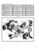
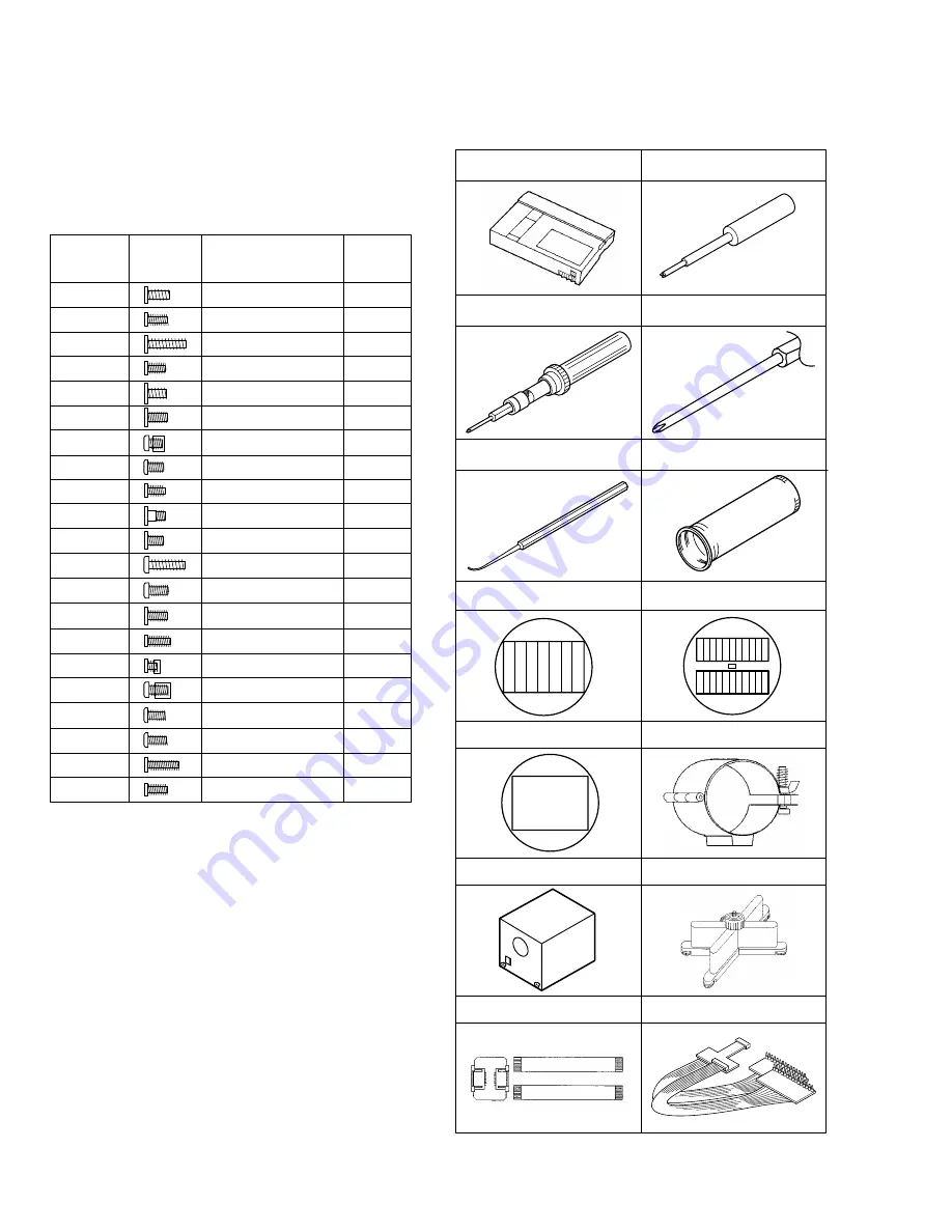
ALIGHMENT TAPE
MC-1
GUIDE DRIVER
YTU94148A
1
2
INF ADJUSTMENT LENS
YTU92001B
CHIP IC REPLACEMENT JIG
PTS40844-2
COLOR BAR CHART
YTU92001-051
GRAY SCALE CHART
YTU92001-052
WHITE BALANCE CHART
YTU92001-053
INF LENS HOLDER
YTU94087
LIGHT BOX
YTU93072A-1
7
8
9
10
11
12
13
14
TORQUE DRIVER
YTU94088
3
4
BIT
YTU94088-003
PATCH CORD
YTU93099A
5
6
CAMERA STAND
YTU93079
JIG CONNECTOR CABLE
YTU93082C
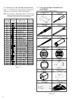
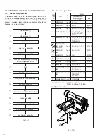
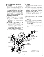
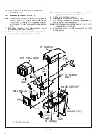
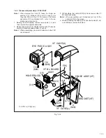
1.1.4 Main screws to deal with disassembly/assembly
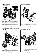
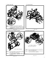
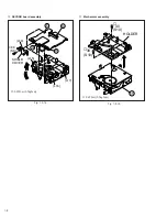
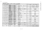
Table 1-1-1 lists screws by their symbols correspond to
those shown in figures of this section “Disassembly”.
Note:
Screw that are asterisked (marked with
✽
) in the
shape column are fixed with screw lock agent. If such
the screw in once removed, never used it again.
Table 1-1-1
SHAPE
COLOR
PARTS NO.
(S1)
(S2)
(S3)
(S4)
(S5)
(S6)
(S7)
(S8)
(S9)
(S10)
(S11)
(S12)
(S13)
(S14)
(S15)
(S16)
(S17)
(S18)
(S19)
SYMBOL
LY30019-014A
QYSLSF2090D
LY30018-044A
YQ43762-5
QYSLSF2055D
BLACK
BLACK
BLACK
BLACK
GOLD
GOLD
GOLD
SILVER
BLACK
GOLD
QYSLSP2030D
BLACK
QYSPSGU2080Z
GOLD
PTY30151-016
SILVER
QYSLSP2040D
BLACK
QYSPSPT1750D BLACK
LY30018-038A
BLACK
LY30018-090A
GOLD
QYSPSGT1735Z
GOLD
(S20)
(S21)
LY30018-058A
SILVER
LY30018-079A
BLACK
LY30018-023A
BLACK
LY30018-050A
LY30018-089A
LY30018-084A
YQ43893-3
LY30018-024A
✽
✽
✽
1.2 TOOLS AND EQUIPMENTS REQUIRED FOR
ADJUSTMENTS
1.2.1 Tools required for adjustments
Table 1-2-1


