1-5
2
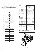
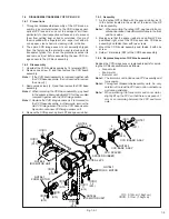
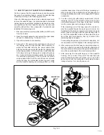
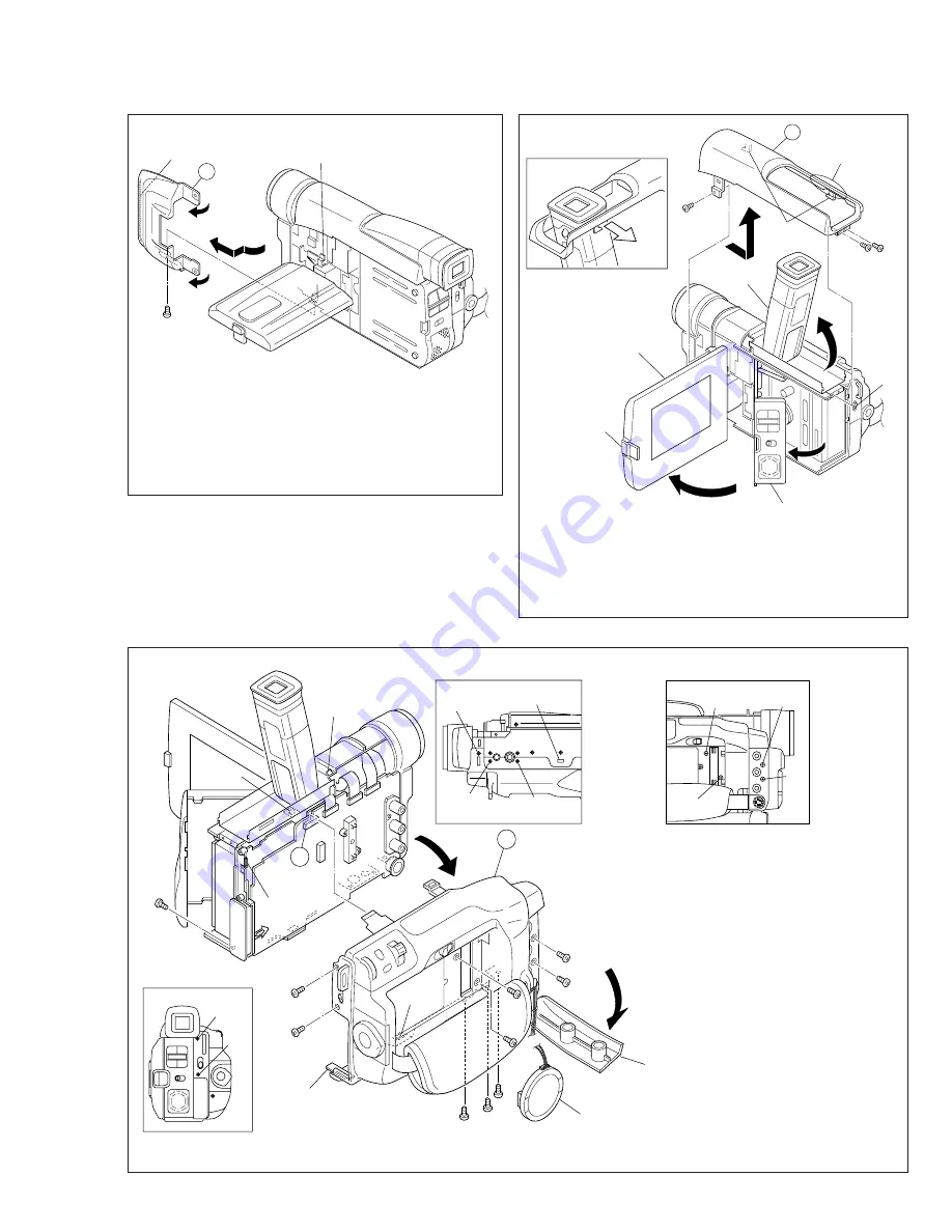
Upper case (1)
Fig.1-3-3
3
Top cover
Fig. 1-3-5
Fig. 1-3-4
4
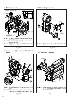
Lower case assembly
Note
1: When dismantling, spread the upper case (1)
slightly outwards not to get it touching the hinge
assembly.
Note
2: When reassembling the upper case (1) to the main
frame, set (L2) inside the front cover assembly.
(L2)
NOTE2
NOTE1
HINGE ASSY
NOTE1
2
3
(S1)
✽
: 0.07N·m (0.7kgf·cm)
6
(S2)
4
(S1)
(L1)
(L3)
5
(S2)
3
NOTE4
NOTE3
NOTE4
OPE COVER UNIT
MONITOR ASSY
E.VF ASSY
(L4)
✽
✽
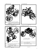
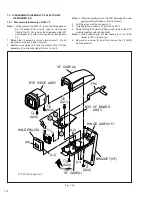
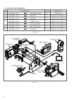
Note
3: When dismantling, pay heed to the hook (L4) not to
damage it.
Note
4: When drawing the top cover out of the E. VF
assembly, spread the frame slightly outwards with
care not to damage any part.
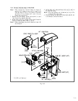
Note
5: Remove the CAP (HOOD)
before proceeding to the
removing work.
Note
6: Remove the cap (RCA) before
proceeding to the removing
work.
Note
7: Be careful not to damage the
FPC and connector because the
FPC is internally connected.
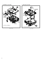
Note
8: Pay heed to the spring not to
lose it.
✽
: 0.07N·m (0.7kgf·cm)
NOTE6
(L5)
CAP
(RCA)
NOTE5
NOTE8
NOTE7
CAP (HOOD)
11
(S1)
13
(S3)
15
(S1)
16
(S1)
14
(S3)
12
(S1)
10
(S1)
9
(S2)
8
(S2)
(L7)
Rear
Bottom
Side
A
BRACKET
(L6)
(L7)
4
11
(S1)
12
(S1)
8
(S2)
10
(S1)
9
(S2)
13
(S3)
14
(S3)
15
(S1)
7
(S2)
16
(S1)
✽
✽
✽


