background image

EN

51

SYSTEM CONNECTIONS

NOTES:

It is recommended to use the AC Adapter as the
power supply instead of the battery pack
(

 pg. 9).

Never connect the PC connection cable and the
DV cable simultaneously to the camcorder.
Connect only the cable you wish to use to the
camcorder.

The date/time information cannot be captured into
the PC.

Refer to the instruction manuals of the PC and
Software.

The still images can also be transferred to a PC
with a DV connector-equipped capture board.

When using a DV cable, be sure to use the
optional JVC VC-VDV206U or VC-VDV204U DV
cable depending on the type of DV connector (4
or 6 pins) on the PC, or use the DV cable provided
with the capture board.

The system may not work properly depending on
the PC or capture board you are using.

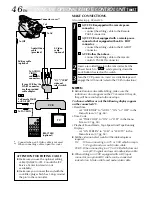
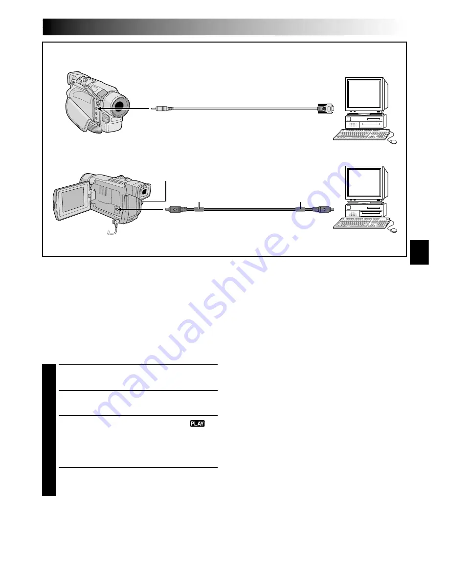
To DV

DV cable
(optional)

To DV
connector

Power Switch

PC with DV
connector

PC

Core filter

OR

Core filter

To
RS-232C

PC connection cable
(optional)

To PC
(DIGITAL
PHOTO)

Connection To A Personal Computer

[A] Using PC connection cable

This camcorder can transfer still images to a PC by
using the optional software HS-V16KIT.

[B] Using DV cable

It is also possible to transfer still images to a PC with
a DV connector by using software equipped with the
PC or commercially available software.

1

Make sure the camcorder and PC are turned off.

2

Connect the camcorder to your PC using the
appropriate cable as shown in the illustration.

3

Turn the camcorder’s Power Switch to “

while pressing down the Lock Button located on
the switch and turn on the PC.
•Refer to the instruction manual of the software

on how to transfer a still image to the PC.

4

When finished, turn off the PC first, then the
camcorder.

[A]Using PC connection cable

[B] Using DV cable

Summary of Contents for GR-DVL140

Page 1: ...52 FOR RECORDING 25 33 USING MENUS FOR DETAILED ADJUSTMENT 34 39 DUBBING 40 41 USING THE OPTIONAL REMOTE CONTROL UNIT 42 50 SYSTEM CONNECTIONS 51 52 REFERENCES 53 71 DETAILS 54 TROUBLESHOOTING 55 59 INDEX 60 64 USER MAINTENANCE 65 CAUTIONS 66 67 TERMS 68 69 SPECIFICATIONS 70 71 Please visit our Homepage on the World Wide Web and answer our Consumer Survey in English only http www jvc victor co jp ...

Page 2: ...tension lead or consult your dealer BE SURE to replace the fuse only with an identical approved type as originally fitted and to replace the fuse cover If nonetheless the mains plug is cut off be sure to remove the fuse and dispose of the plug immediately to avoid possible shock hazard by inadvertent connection to the mains supply If this product is not supplied fitted with a mains plug then follo...

Page 3: ...mpt to use the equipment DO ensure that all electrical connections including the mains plug extension leads and interconnections between pieces of equipment are properly made and in accordance with the manufacturer s instructions Switch off and withdraw the mains plug when making or changing connections DO consult your dealer if you are ever in doubt about the installation operation or safety of y...

Page 4: ... use a tripod on unsteady or unlevel surfaces It could tip over causing serious damage to the camcorder CAUTION Connecting cables Audio Video S Video etc to the camcorder and leaving the unit on top of the TV is not recommended as tripping on the cables will cause the camcorder to fall resulting in damage 䡲 This camcorder is designed exclusively for the digital video cassette Only cassettes marked...

Page 5: ...amcorder Core Filter x 3 for optional S Video cable Editing cable and PC Connection cable provided with optional HS V16KIT software 墌 pg 6 for attachment NOTE In order to maintain optimum performance of the camcorder provided cables may be equipped with one or more core filter If a cable has only one core filter the end that is closest to the filter should be connected to the camcorder ...

Page 6: ...nu appears 4 Rotate the MENU BRIGHT wheel to select OFF and press it 5 Rotate the MENU BRIGHT wheel to select 1RETURN and press it twice The normal screen appears NOTE If you do not detach the Lens Cap you cannot see the actual changes of the Automatic Demonstration activated on the LCD monitor or viewfinder MODE DEMO ON OFF MENU BRIGHT Wheel Sub Menu Lock Button Power Switch How To Attach The Cor...

Page 7: ...STARTED GETTING STARTED CONTENTS Power 8 9 Grip Adjustment 10 Viewfinder Adjustment 10 Shoulder Strap Attachment 11 Tripod Mounting 11 Date Time Settings 12 Loading Unloading A Cassette 13 Recording Mode Setting 14 ...

Page 8: ... The Battery Pack slide BAT RELEASE and pull out the battery pack NOTES If the protective cap is attached to the battery pack remove it first During charging the camcorder cannot be operated Charging is not possible if the wrong type of battery is used When charging the battery pack for the first time or after a long storage period the CHARGE lamp may not light In this case remove the battery pack...

Page 9: ...the battery or its terminals to come in contact with metals as this can result in a short circuit and possibly start a fire The Benefits Of Lithium Ion Batteries Lithium ion battery packs are small but have a large power capacity However when one is exposed to cold temperatures below 10 C its usage time becomes shorter and it may cease to function If this happens place the battery pack in your poc...

Page 10: ...tton and Power Switch and Power Zoom Lever Be sure to fasten the Velcro strip to your preference Viewfinder Adjustment 1 Set the Power Switch to or while pressing down the Lock Button located on the switch 2 Turn the Dioptre Adjustment Control until the indications in the viewfinder are clearly focused Dioptre Adjustment Control Power Switch GETTING STARTED cont Power Zoom Lever Recording Start St...

Page 11: ...t 3 located under the Grip Strap Confirm the strap is not twisted CAUTION When attaching the camera to a tripod extend its legs to stabilise the camcorder It is not advised to use small sized tripods This may cause damage to the unit by falling over 1 To attach the camera to a tripod align the direction stud and screw to the mounting socket and stud hole on the camera Then tighten the screw clockw...

Page 12: ... select DISPLAY Press it and the DISPLAY Menu appears 4 Rotate the MENU BRIGHT wheel to select CLOCK ADJ Press it and day is highlighted Rotate the MENU BRIGHT wheel to input the day Press it Repeat to input the month year hour and minute Rotate the MENU BRIGHT wheel to select 1RETURN and press it twice The Menu Screen closes NOTE Even if you select CLOCK ADJ if the parameter is not highlighted th...

Page 13: ... still does not open turn the camcorder off then on again If the tape does not load properly open the cassette holder cover fully and remove the cassette A few minutes later insert it again When the camcorder is suddenly moved from a cold place to a warm environment wait a short time before opening the cassette holder cover Closing the cassette holder cover before the cassette holder comes out may...

Page 14: ...HT wheel and press it Rotate the MENU BRIGHT wheel to select 1RETURN and press it twice The Menu Screen closes Audio Dubbing 墌 pg 50 is impossible on a tape recorded in the LP mode LP Long Play is more economical providing 1 5 times the recording time NOTES If the recording mode is switched during recording the playback picture will be blurred at the switching point It is recommended that tapes re...

Page 15: ...S BASIC RECORDING 16 19 Basic Recording 16 Journalistic Shooting 17 Self Recording 17 Operation Mode 17 Zooming 18 Time Code 19 BASIC PLAYBACK 20 23 Normal Playback 20 Still Playback 20 Shuttle Search 20 Frame By Frame Playback 20 Blank Search 21 Connections 22 23 ...

Page 16: ...d the camcorder enters the Record Standby mode PAUSE is displayed 3 Press the Recording Start Stop Button appears while recording is in progress To Stop Recording press the Recording Start Stop Button The camcorder re enters the Record Standby mode To Adjust The Brightness Of The Display rotate the MENU BRIGHT wheel until the bright level indicator on the display moves and the appropriate brightne...

Page 17: ...ur preference using the Power Switch Power Switch Position Manual Allows you to set various recording functions using the Menus If you want more creative capabilities than Full Auto recording try this mode Full Auto Allows you to record using NO special effects or manual adjustments Suitable for standard recording OFF Allows you to switch off the camcorder Allows you to play back a recording on th...

Page 18: ...g the manual focus 墌 pg 25 then zoom in or out in Record mode Zooming is possible to a maximum of 150X or it can be switched to 10X magnification using the optical zoom 墌 pg 35 Zoom magnification of over 10X is done through Digital image processing and is therefore called Digital Zoom During Digital zoom the quality of image may suffer Digital zoom cannot be used when digital image processing such...

Page 19: ...ing using a partially recorded tape When shooting on a blank portion located partway through the tape When shooting again after shooting a scene then opening closing the cassette holder cover Recording From The Middle Of A Tape 1 Play back a tape or use Blank Search 墌 pg 21 to find the spot at which you want to start recording then engage the Still Playback mode 墌 pg 20 2 Set the Power Switch to o...

Page 20: ...ppear During Stop mode none of the indications are displayed When a cable is connected to the AV connector the sound is not heard from the speaker Power Zoom Lever VOL Speaker Lock Button Still Playback Pauses during playback 1 Press 4 6 during playback 2 To resume normal playback press 4 6 again If still playback continues for more than about 3 minutes the camcorder s Stop mode is automatically e...

Page 21: ... To cancel Blank Search midway press 5 NOTES In step 3 if the current position is at a blank portion the camcorder searches in the reverse direction and if the current position is at a recorded portion the camcorder searches in the forward direction Blank Search does not work if HEAD CLEANING REQUIRED USE CLEANING CASSETTE has appeared with the tape If the beginning or end of the tape is reached d...

Page 22: ...e CVBS When connecting to a TV or VCR which does not accept Y C signals and uses an audio video cable Camcorder Use the provided Audio Video cable and optional S Video cable To AV TV or VCR Yellow To IN White to AUDIO L Red to AUDIO R Audio Video cable mini plug to RCA plug provided The Audio cable is not required for watching still images only To S To AV White to AUDIO L IN Red to AUDIO R IN To S...

Page 23: ...to ON or OFF in the Menu Screen 墌 pg 38 Playback Sound Mode Tape Speed And Tape Running Displays for video playback set ON SCREEN to LCD or LCD TV in the Menu Screen 墌 pg 38 NOTES It is recommended to use the AC Adapter as the power supply instead of the battery pack 墌 pg 9 To monitor the picture and sound from the camcorder without inserting a tape set the camcorder s Power Switch to or then set ...

Page 24: ...eration 33 USING MENUS FOR DETAILED ADJUSTMENT 34 39 For Recording Menu 34 37 For Playback Menu 38 39 DUBBING 40 41 Dubbing To A VCR 40 Dubbing To A Video Unit Equipped With A DV Connector 41 USING THE OPTIONAL REMOTE CONTROL UNIT 42 50 Installing The Battery 42 Playback Zoom 44 Random Assemble Editing 45 48 For More Accurate Editing 49 Audio Dubbing 50 SYSTEM CONNECTIONS 51 52 Connection To A Per...

Page 25: ...se to the lens zoom out first 墌 pg 18 If zoomed in in the auto focus mode the camcorder may automatically zoom out depending on the distance between the camcorder and the subject This will not occur when TELE MACRO 墌 pg 36 is activated FEATURE Manual Focus PURPOSE To obtain correct focus OPERATION 1 If you are using the viewfinder you should already have made the necessary viewfinder adjustments 墌...

Page 26: ...d during recording or during Record Standby Some modes of Programme AE special effects cannot be used during Night Scope MENU BRIGHT Wheel Display Night Scope Makes dark subjects or areas even brighter than they would be under good natural lighting Although the recorded image is not grainy it may look as if it is strobing due to the slow shutter speed 1 Set the Power Switch to while pressing down ...

Page 27: ...ter speed is fixed at 1 120th of a second The flickering that occurs when shooting under a fluorescent light or mercury vapour lamp is reduced This setting allows fast moving images to be captured one frame at a time for vivid stable slow motion playback The faster the shutter speed the darker the picture becomes Use the shutter function under good lighting conditions SNOW Compensates for subjects...

Page 28: ...cture Wipe or Dissolve works when recording is started 1 Follow steps 1 through 4 above 2 If you select Picture Wipe Dissolve during recording press the Recording Start Stop Button when one scene is finished The point at which the scene ended is stored in memory If you select Picture Wipe Dissolve during Record Standby mode press the Recording Start Stop Button to start recording and press it agai...

Page 29: ...es out from top to bottom leaving a black screen Wipe in from the centre of a black screen toward the top and bottom or wipe out from the top and bottom toward the centre leaving a black screen The new scene gradually appears as the old one gradually disappears The new scene wipes in over the previous one from the upper right corner to the lower left corner The next scene gradually wipes in from t...

Page 30: ... 墌 pg 31 then press it Rotate the MENU BRIGHT wheel to select 1RETURN and press it twice The Menu Screen closes SNAPSHOT RECORDING 1 Press SNAPSHOT If you press during Record Standby PHOTO appears and a still image will be recorded for approx 6 seconds then the camcorder re enters the Record Standby mode If you press during Recording PHOTO appears and a still image will be recorded for approx 6 se...

Page 31: ...ressed when DIS is set to ON 墌 pg 35 the Stabiliser will be disabled During tape playback as well all snapshot modes are available However the shutter sound is not heard During Snapshot recording the image displayed in the viewfinder may be partially missing However there is no effect in the recorded image When a cable is connected to the AV connector the shutter sound is not heard from the speake...

Page 32: ... is engaged Iris Lock Use this function in the following situations When shooting a moving subject When the distance to the subject changes so its size in the LCD monitor or the viewfinder changes such as when the subject is backing away When shooting on a reflective natural background such as at the beach or when skiing When shooting objects under a spotlight When zooming When the subject is clos...

Page 33: ...hen Sepia or Monotone 墌 pg 27 is activated Manual White Balance Operation Perform Manual White Balance when shooting under various types of lighting 1 Follow steps 1 through 4 of the white balance adjustment and select MWB 2 Hold a sheet of plain white paper in front of the subject Adjust zoom or position yourself so that the white paper fills the screen 3 Press the MENU BRIGHT wheel in until begi...

Page 34: ...ies many of the more detailed camcorder settings 墌 pg 35 37 1 Set the Power Switch to while pressing down the Lock Button located on the switch 2 Press the MENU BRIGHT wheel in The Menu Screen appears 3 Rotate the MENU BRIGHT wheel to select the desired function menu and press it The selected function menu appears 4 Function menu setting depends on the function If you have selected WIPE FADER PROG...

Page 35: ...stment The overall appearance may be grainy but the image is bright The shutter speed is automatically adjusted 1 25 1 200 sec Shooting a subject in low or poor lighting at 1 25 sec shutter speed provides a brighter image than in the AGC mode but the subject s movements are not smooth or natural The overall appearance may be grainy While the shutter speed is being automatically adjusted is display...

Page 36: ...s are inserted at the top and bottom of the screen and the image appears like a letterboxed 16 9 movie For playback on TVs with an aspect ratio of 16 9 Naturally expands the image to fit the screen without distortion appears When using this mode refer to your wide screen TV s instruction manual During playback recording on 4 3 TVs LCD monitor viewfinder the image is elongated vertically Disengages...

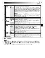
Page 37: ...e camcorder power is turned off If DEMO MODE remains ON some functions will not be available After viewing demo set to OFF Does not reset all settings to the factory preset Resets all settings to the factory preset Keeps the camcorder s display except the date time and time code from appearing on the connected TV screen Makes the camcorder s display appear on screen when the camcorder is connected...

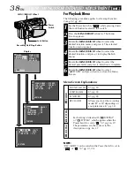
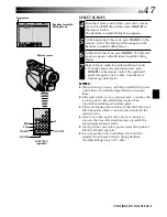
Page 38: ... menu appears 4 Rotate the MENU BRIGHT wheel to select the desired function and press it to display the Sub Menu 5 Rotate the MENU BRIGHT wheel to select the desired parameter and press it Selection is complete 6 Rotate the MENU BRIGHT wheel to select 1RETURN and press it twice to close the Menu Screen Display Power Switch MENU BRIGHT Wheel Lock Button Recording Start Stop Button NOTE REC MODE can...

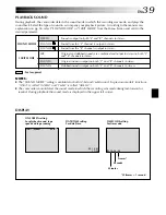
Page 39: ...t the sound mode in which the recording was made during fast forward or rewind During playback the sound mode is displayed in the upper left corner SOUND MODE 12BIT MODE Factory preset STEREO SOUND L SOUND R MIX SOUND 1 SOUND 2 Sound is output on both L and R channels in stereo Sound from the L channel is output in stereo Sound from the R channel is output in stereo Original and dubbed sounds are ...

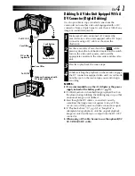
Page 40: ...u start dubbing make sure that the indications do not appear on the connected TV If they do they are being recorded onto the new tape Set the video out select switch of the cable adapter as required Y C When connecting to a TV or VCR which accepts Y C signals and uses an S Video cable CVBS When connecting to a TV or VCR which does not accept Y C signals and uses an audio video cable To choose whet...

Page 41: ... playback on the monitor engage the DV connector equipped video unit s record mode from the spot on the source tape you want to begin recording NOTES It is recommended to use the AC Adapter as the power supply instead of the battery pack 墌 pg 9 If a blank portion or disturbed image is played back on the player during dubbing the dubbing may stop so that an unusual image is not dubbed Even though t...

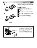
Page 42: ...tion Remote Control Unit RM V700U can operate this camcorder from a distance as well as the basic operations Playback Stop Pause Fast Forward and Rewind of your VCR Installing The Battery The remote control uses one lithium battery CR2025 1 Pull out the battery holder while sliding the lock hole Pinch the release tab and pull out the battery holder 2 Insert the battery in the holder and be sure to...

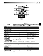
Page 43: ...T Buttons This function is unavailable with this camcorder RM V700U optional 1 9 7 5 3 2 4 6 8 0 Functions With the camcorder s Power Switch set to the camera position or Transmits the beam signal Functions the same as the Recording Start Stop Button on the camcorder Zoom in out 墌 pg 18 With the camcorder s Power Switch set to 墌 pg 46 墌 pg 45 Forward Forward Shuttle Search 墌 pg 20 Rewind Reverse S...

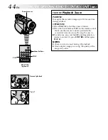
Page 44: ...remote control is pointed at the camcorder s remote sensor Pressing T zooms in 䡲To end zoom press and hold W until magnification returns to normal Or press STOP 5 and then press PLAY 4 NOTES Zoom can also be used during still playback Due to digital image processing the quality of the image may suffer Remote sensor Press T Normal playback Zoom Buttons PLAY STOP USING THE OPTIONAL REMOTE CONTROL UN...

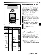
Page 45: ...to press VCR CTL for this one You are now ready to try Random Assemble Editing IMPORTANT Although the MBR is compatible with JVC VCRs and those of many other makers it may not work with yours or may offer limited functions NOTES If the VCR s power does not come on in step 1 try another code from the VCR CODE LIST Some brands of VCR do not come on automati cally In this case turn the power on manua...

Page 46: ...N or OFF in the Menu Screen 墌 pg 38 Playback Sound Mode Tape Speed And Tape Running Displays set ON SCREEN to LCD or LCD TV in the Menu Screen 墌 pg 38 Set the video out select switch of the cable adapter as required Y C When connecting to a TV or VCR which accepts Y C signals and uses an S Video cable CVBS When connecting to a TV or VCR which does not accept Y C signals and uses an audio video cab...

Page 47: ... from the most recently registered point NOTES When choosing a scene set Edit In and Edit Out points so that there is a relatively large difference between them If the search time for an in point exceeds 5 minutes the recording deck s Record Standby mode will be cancelled and editing will not take place If there are blank portions before or after the Edit In and Edit Out points a blue screen may b...

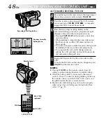
Page 48: ...e and the VCR enters its Record Pause mode If you do not register an Edit Out point the tape will be dubbed all the way to the end automatically If you operate the camcorder during automatic editing the VCR will enter its Record Pause mode and automatic editing will stop 1 11Engage the Stop modes for the camcorder and the VCR To make the R A Edit counter display disappear press ON OFF on the remot...

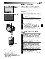
Page 49: ...is slow to start recording Random Assemble Editing Menu Programme 1 Remote sensor VIDEO Menu ADJUSTMENT OF VCR CAMCORDER TIMING 4 Point the remote control at the camcorder s remote sensor and press ON OFF to make the Random Assemble Editing menu disappear then press the MENU BRIGHT wheel in The Menu Screen appears 5 Rotate the MENU BRIGHT wheel to select VIDEO and push it The VIDEO Menu appears Th...

Page 50: ...ed sound during playback set 12BIT MODE to SOUND 2 or MIX in the Menu Screen 墌 pg 38 39 NOTES Sound is not heard from the speaker during Audio Dubbing When editing onto a tape that was recorded at 12 bit the old and new soundtracks are recorded separately If you dub onto a blank space on the tape the sound may be disrupted Make sure you only edit recorded areas If feedback or howling occurs during...

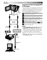
Page 51: ... you are using To DV DV cable optional To DV connector Power Switch PC with DV connector PC Core filter OR Core filter To RS 232C PC connection cable optional To PC DIGITAL PHOTO Connection To A Personal Computer A Using PC connection cable This camcorder can transfer still images to a PC by using the optional software HS V16KIT B Using DV cable It is also possible to transfer still images to a PC...
Page 52: ...GV DT3 to the printer s PC connector and the PC s RS 232C connector 4 Turn the camcorder s Power Switch to while pressing down the Lock Button located on the switch and turn on the other units NOTES It is recommended to use the AC Adapter as the power supply instead of the battery pack 墌 pg 9 If Still Playback Fast Forward or Rewind is attempted with the camcorder connected to a video unit via the...

Page 53: ...3 REFERENCES REFERENCES CONTENTS DETAILS 54 TROUBLESHOOTING 55 59 INDEX 60 64 Controls Connectors And Indicators 60 61 Indications 62 64 USER MAINTENANCE 65 CAUTIONS 66 67 TERMS 68 69 SPECIFICATIONS 70 71 ...

Page 54: ... monitor outdoors in direct sunlight the LCD monitor may be difficult to see If this happens use the viewfinder instead The cassette holder cannot be opened unless a power supply is attached There may be a delay after you open the cassette holder cover until the cassette holder opens Do not use force Once the cassette holder is closed it recedes automatically Wait until it recedes completely befor...

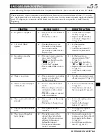
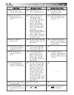
Page 55: ...urces behind the subject The Sepia or Monotone mode is activated 1 Connect the AC Adapter securely 墌 pg 9 Replace the dead battery with a fully charged one 墌 pg 8 9 2 Set the date time 墌 pg 12 Consult your nearest JVC dealer for replacement 3 Set the tape s erase protection tab to REC 墌 pg 13 Set the Power Switch to or 墌 pg 17 Replace with new cassette 墌 pg 13 Close the cassette holder cover 4 Tur...

Page 56: ...end of the last selected scene for editing the Power Switch was set to OFF The power is off 9 Press the BACKLIGHT Button 墌 pg 32 10 Set PROGRAM AE to SPOTLIGHT in the Menu Screen 墌 pg 26 11 Set ZOOM to 40X or 150X in the Menu Screen 墌 pg 35 Disengage the VIDEO ECHO mode 墌 pg 18 27 Wait until the Picture Wipe or Dissolve effects are completed 墌 pg 18 28 12 Turn off Sepia and Mono tone 墌 pg 26 28 13...

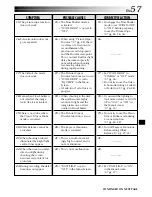
Page 57: ...or during rapid panning 17 The Picture Wipe or Dissolve functions are in use WIDE MODE is set to SQUEEZE in the Menu Screen A Fade In or Fade Out is in progress 18 When shooting in the dark the unit becomes highly sensitive to light and the image takes on an effect similar to Slow Shutter 19 The Picture Wipe or Dissolve function is in use 20 The Sepia or Monotone mode is activated 21 This is a res...

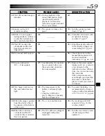
Page 58: ...r bright spots of light red green or blue may appear constantly on the LCD monitor or the viewfinder These spots are not recorded on the tape This is not due to any defect of the unit Effective dots more than 99 99 30 This is normal 31 The Power Switch is set to or 24 Set TIME CODE to ON in the Menu Screen 墌 pg 37 38 25 Adjust the brightness and angle of the LCD monitor 墌 pg 16 17 26 Close the LCD...

Page 59: ...this case the camcorder s functions become unusable 38 The temperature of the battery is extremely high low Charging is difficult in places subject to extremely high low temperatures 39 This is not a malfunction 40 The DV cable was plugged unplugged with power turned on 32 33 Turn the speaker volume down 墌 pg 20 34 Clean the video heads with an optional cleaning cassette 墌 pg 67 35 Wipe them gentl...
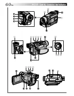
Page 60: ...60EN INDEX Controls Connectors And Indicators P L A Y O FF 1 u e y 3 4 5 6 7 o p r R W T E Q q 0 8 9 i 2 t w ...

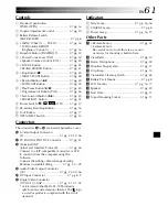
Page 61: ...OTO Connector 墌 pg 51 J Terminal JLIP Joint Level Interface Protocol 墌 pg 46 Connect to a JLIP compatible camcorder or VCR to control it from the computer using the Software Connect the editing cable when performing Random Assemble Editing 墌 pg 45 49 Audio Video Output Connector AV 墌 pg 22 40 46 DC Input Connector 墌 pg 8 9 q Digital Video Connector DV OUT i Link 墌 pg 41 51 52 i Link refers to the ...

Page 62: ...in the Squeeze or Cinema mode 墌 pg 36 INDEX Indications LCD Monitor Viewfinder Indications During Recording 3 40x B 2 R 0 W I G 5 P H 5 T T L 1 P 1 5 1 0 0 R min E 0 0 C 1 0 8 0 9 2 1 3 4 5 7 6 Appears during zooming Zoom level indicator 墌 pg 18 Displays the recording mode SP or LP 墌 pg 14 Displays the tape remaining time 墌 pg 16 REC appears during recording PAUSE appears during Record Standby mod...

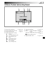
Page 63: ...uttle search 2 Rewind Shuttle search 6 Pause 64 Forward slow motion 16 Reverse slow motion e Audio Dubbing 6e Audio Dubbing Pause 5 Displays the date time 墌 pg 38 39 6 BRIGHT Displays the brightness of the LCD monitor 墌 pg 16 VOLUME Displays the speaker volume 墌 pg 20 The level indicator moves 7 Displays the time code 墌 pg 38 39 1 L 2B 2 I 0 T 2 S B V 1 O L O U A L 2 N N U 5 D K M 1 E SEARCH 1 P 1...

Page 64: ...e time is erased Consult your nearest JVC dealer for replacement Appears for 5 seconds after power is turned on if the lens cap is attached Appears if Audio Dubbing is attempted on a blank portion of a tape 墌 pg 50 Appears if Audio Dubbing is attempted on a tape recorded in the LP mode 墌 pg 50 Appears if Audio Dubbing is attempted on a tape recorded in 16 bit audio 墌 pg 50 Appears if A DUB e on th...

Page 65: ...n the interior of the viewfinder with it 2 6 Close the hatch Tilt the viewfinder back to the horizontal position NOTES Avoid using strong cleaning agents such as benzine or alcohol Cleaning should be done only after the battery pack has been removed or other power units have been disconnected Mould may form if the lens is left dirty When using a cleaner or chemically treated cloth refer to the cau...

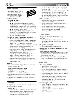
Page 66: ...make sure the cassette bears the Mini DV mark be aware that recording onto prerecorded tapes automatically erases the previously recorded video and audio signals Terminals make sure the cassette is positioned properly when inserting do not load and unload the cassette repeatedly without allowing the tape to run at all This slackens the tape and can result in damage do not open the front tape cover...

Page 67: ...ns directed at extremely bright objects for long periods expose the lens to direct sunlight carry it by holding the LCD monitor or the viewfinder swing it excessively when using the shoulder strap or the grip 5 Dirty heads can cause the following problems No picture during playback Blocks of noise appear during playback During recording the Head Clog Warning indicator appears In such cases use an ...

Page 68: ...Scope 墌 pg 26 A AC Adapter 墌 pg 8 9 Audio Dubbing 墌 pg 50 Auto Date 墌 pg 37 Auto Focus 墌 pg 25 Auto Shut off 墌 pg 16 20 B Backlight Compensation 墌 pg 32 Battery Low 墌 pg 64 Battery Pack 墌 pg 8 9 66 Beep 墌 pg 36 Blank Search 墌 pg 21 Brighten The LCD Monitor 墌 pg 16 C Channels Left Right 墌 pg 39 Charge The Battery Pack 墌 pg 8 Cinema 墌 pg 36 Classic Film 墌 pg 27 Clean The Camcorder 墌 pg 65 Connection...

Page 69: ...7 Set Remote Control VCR Code 墌 pg 45 Shuttle Search 墌 pg 20 Shutter Speed 墌 pg 27 Slow Shutter 墌 pg 27 Snapshot 墌 pg 30 Snapshot Mode 墌 pg 30 Snow 墌 pg 27 Sound Mode 墌 pg 35 38 39 Speaker Volume 墌 pg 20 Specifications 墌 pg 70 71 Sports 墌 pg 27 Spotlight 墌 pg 27 Squeeze 墌 pg 36 Still Playback 墌 pg 20 Strobe 墌 pg 27 T Tally 墌 pg 36 Tele Macro 墌 pg 36 Time Code 墌 pg 19 37 38 39 Tripod Mounting 墌 pg ...

Page 70: ...or 2 5 diagonally measured LCD panel TFT active matrix system Viewfinder Electronic viewfinder with 0 24 black white LCD Speaker Monaural For Digital Video Camera Format DV format SD mode Signal format PAL standard Recording Playback format Video Digital component recording Audio PCM digital recording 32 kHz 4 channel 12 bit 48 kHz 2 channel 16 bit Cassette Mini DV cassette Tape speed SP 18 8 mm s...

Page 71: ...o 240 V 50 Hz 60 Hz Output DC 11 V 1 A Dimensions W x H x D 59 mm x 31 mm x 84 mm Weight Approx 140 g not including Power Cord Specifications shown are for SP mode unless otherwise indicated E O E Design and specifications subject to change without notice ...

Page 72: ...COPYRIGHT 2001 VICTOR COMPANY OF JAPAN LTD EG Printed in Japan 0201HOV UN YP VICTOR COMPANY OF JAPAN LIMITED EN GR DVL140 ...

Reviews: