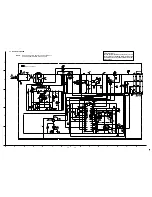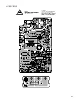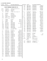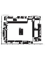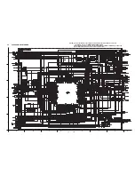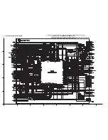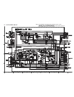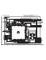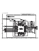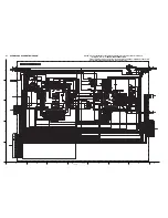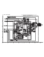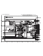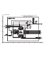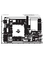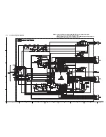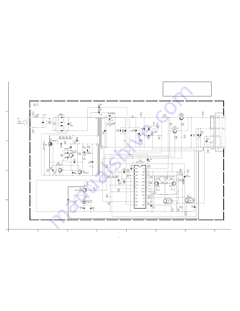
6.2 SCHEMATIC DIAGRAM
NOTE:
When ordering parts, be sure to order according to
the Part Number indicated in the Parts List.
6-2
6-3
Safety precautions
The components identified by the symbol
!
are criti-
cal for safety. For continued safety, replace safety
critical components only with manufacturer’s recom-
mended parts.
A
B
C
D
E
F
G
1
2
3
4
5
SV
CN2
TERMINAL
R57
10
C36
0.22
µ
C35
0.22
TP15
TP16
0.22
MIAN & TERMINAL
R60
OPEN
SV
AC110
0.068
1221304
8.45k
OPEN
OPEN
Q27
OPEN
OPEN
OPEN OPEN
OPEN
OPEN
OPEN
OPEN
Summary of Contents for GR-DVM90U
Page 45: ...5 4 3 2 1 A B C D E F G H 4 1 BOARD INTERCONNECTIONS 4 3 4 4 ...
Page 75: ...5 4 3 2 1 A B C D E F G H 4 37 POWER SYSTEM BLOCK DIAGRAM 4 79 4 80 ...
Page 76: ...5 4 3 2 1 A B C D E F G H 4 38 VIDEO SYSTEM BLOCK DIAGRAM 4 81 4 82 ...
Page 77: ...5 4 3 2 1 A B C D E F G H 4 39 REGULATOR SYSTEM BLOCK DIAGRAM 4 83 4 84 ...


