1-10
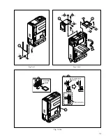
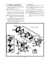
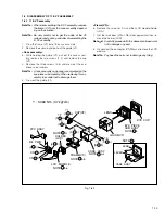
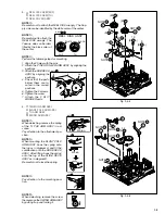
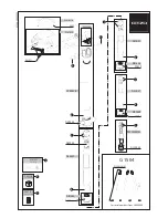
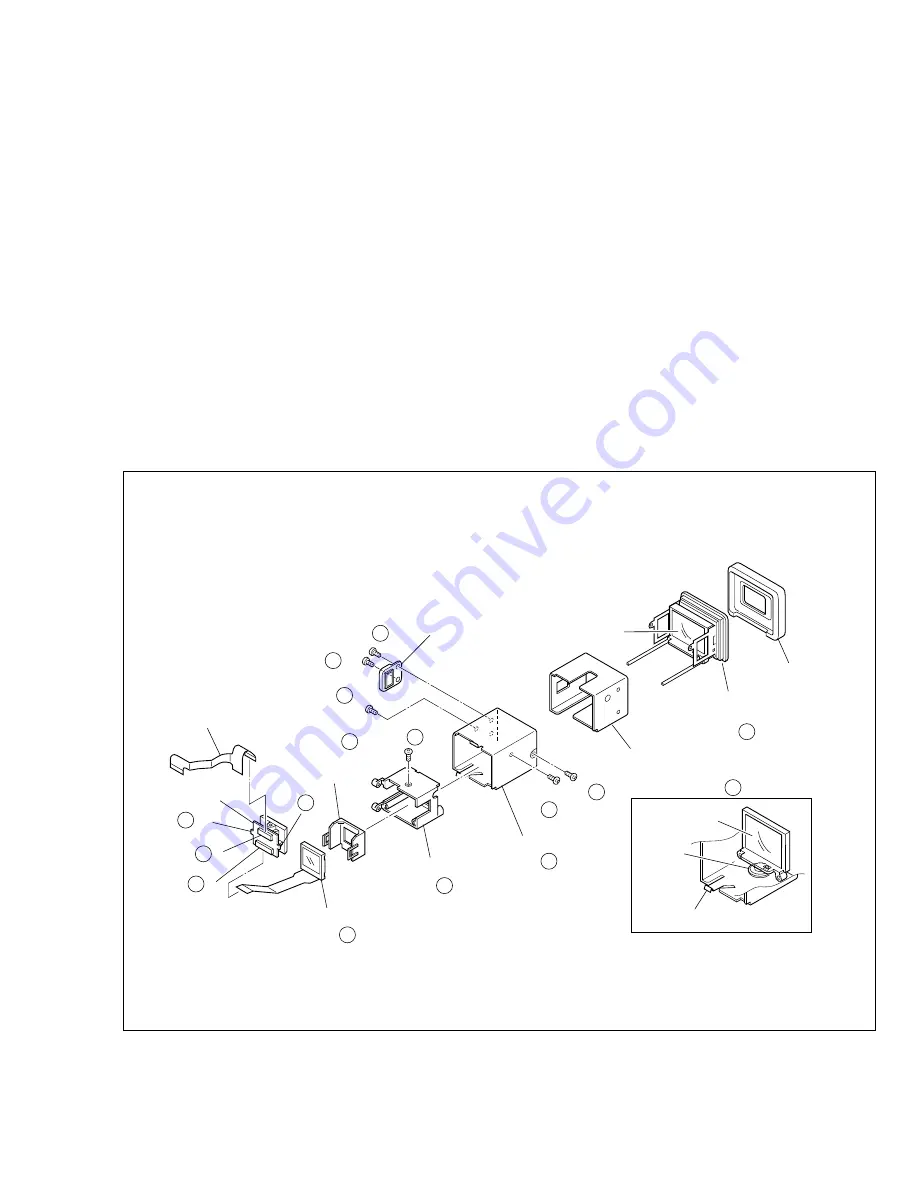
Fig. 1-6-1
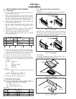
1.6 DISASSEMBLY OF
#
E. VF ASSEMBLY
1.6.1
#
E. VF assembly
Note
#
a:
When disassembling the E. VF assembly, remove
the frame (VF) from the case assembly depend-
ing on the situation.
Note
#
b:
Be very careful not to get the inside of the VF
soiled or dusty during and after disassembling the
E. VF assembly.
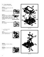
1. Draw the frame (VF) out of the case assembly.
2. Remove the eyecup and pull out the guide (VF).
<Case assembly>
3. While holding the guide (VF), pull out the case assem-
bly, remove the two screws (1, 2) and remove the cap
(VF).
4. Remove the three screws (3-5) and draw out the eye-
piece sub assembly.
Note
#
c:
A lens assembly and a lever are mounted on the
eye-piece sub assembly. When removing this as-
sembly, be careful not to damage them.
5. Draw out the guide (VF).
<Frame (VF)>
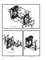
6. Remove the screw (6) first and then LCD module/holder
(LCD).
7. Get the two hooks (L
#
a, L
#
b) disengaged and then re-
move the holder (LCD).
Note
#
d:
Carefully proceed with the above-mentioned work
not to damage any part.
8. Disconnect the connector (CN
#
b) and remove the LCD
module.
Note
#
e:
Pay heed the parts not to damage any thing.
(S
a)
1
EYE CUP
13
(S
a)
2
13
(L
B/L PWB
a)
13
CN
a
13
(S
b)
3
13
(S
c)
6
13
(S
b)
5
13
(S
b)
4
13
NOTE
d
13
NOTE
b,e
13
NOTE
a,b
13
NOTE
a,c
13
NOTE
c
13
NOTE
c
13
EYE PIECE
SUB ASSY
LENS
GUIDE(VF)
CASE ASSY
CASE ASSY
FRAME(VF)
HOLDER
(LCD)
FPC ASSY
CAP(VF)
LCD MODULE
(L
b)
13
CN
b
13
LENS
LEVER
∗
∗
∗
∗
∗
∗
∗
: 0.069 N
•
m (0.7 kgf
•
cm)


