background image

Summary of Contents for GVT0294-006B

Page 1: ...RO COMPONENT SYSTEM Consists of CA UXJ51 and SP UXJ51 TM For customer use Enter below the Model No and Serial No which are located either on the rear bottom or side of the cabinet Retain this information for future reference Model No Serial No ...

Page 2: ...s plug to shut the power off completely the STANDBY lamp goes off The MAINS plug or an appliance coupler is used as the disconnect device the disconnect device shall remain readily operable When the System is on standby the STANDBY lamp lights red When the System is turned on the STANDBY lamp goes off The power can be remote controlled CAUTION To reduce the risk of electrical shocks fire etc 1 Do ...

Page 3: ...ilation Correcte Pour éviter tout risque de choc électrique et d incendie placez l appareil en respectant ce qui suit 1 Avant Rien ne doit gêner le dégagement 2 Flancs Dessus Arrière Aucun obstacle ne doit être placé dans les zones indiquées par les dimensions dans l illustration 3 Dessous Poser l appareil sur une surface plate Laissez suffisamment d espace pour que la ventilation puisse s effectu...

Page 4: ...upports for USB connection analog input and digital input External Input The system supports the playback of a USB flash memory and USB mass storage class compliant digital audio player In addition as well as analog input terminals for cassette decks the UX J51 also features a sampling rate converter compliant digital input terminal for digital tuners etc Choose your favorite audio quality Digital...

Page 5: ... iPod USB External Components D AUDIO This chapter explains how to store and maintain your system so that it continues to give pleasure for many years to come Audio Settings P 43 This chapter explains how to tailor the system to your audio preferences CONEQ Acoustic Equalizer Digital Signal Processor BALANCE Component Settings P 53 This chapter explains how to select the settings for the system Se...

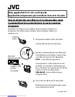
Page 6: ... the original carton and packing materials in case you need to move or ship the unit in the future Keep this manual handy for future reference RM SUXJ51U Do not damage the cable by applying excessive force when winding z 5 cm 2 in USB cable not supplied Core filter 1 How to attach the core filter to the USB cable Attach the core filter to the USB cable to reduce interference Stopper Release the st...

Page 7: ... the best acoustic effect Observe the following cautions when installing the system Insufficient heat radiation may build up internal heat and cause a malfunction or fire hazard Do not place any object on the system that may hinder heat radiation Do not place the system upside down or lay it on its side Do not cover the system with a cloth or place it on a carpet or blanket Do not place the system...

Page 8: ... all the way into the AC wall outlet z Caution for Connection Do not plug the AC power cord into an AC wall outlet until all the connections are completed Before disconnecting any cords or cables always turn the system off and unplug the power cord from AC wall outlet Caution for outdoor antenna installation Since antenna installation requires skill and experience always consult your dealer before...

Page 9: ...gether Mistakenly reversing the positive and negative polarity will result in unnatural sound and unclear sound Connecting the speakers Microcomputer malfunctions If the system is connected correctly and still does not operate normally or shows display errors reset the microcomputer P 67 The antenna supplied with the system is for indoor use Place it as far as possible away from the main unit your...

Page 10: ...push down the Dock adapter into the unit with its slit facing toward the unit until it clicks USB Connect USB flash memory or USB mass storage class compliant digital audio players to the USB port after opening the cover on the main unit Depending on the device being connected it may take some time for the system to recognize it Some USB devices may not be recognized or cannot play certain files W...

Page 11: ...IGITAL IN REC OUT PLAY IN D AUDIO IN REC OUT Audio IN Connect the audio IN terminals on components such as cassette decks to the AUX REC OUT terminal on the rear panel of the main unit AUX REC OUT outputs an analog audio signal z AUX IN SPEAKERS DIGITAL OUT DIGITAL IN REC OUT PLAY IN D AUDIO IN SUB WOOFER PRE OUT R L R L PLAY IN R L Cassette deck etc Audio OUT Connect the audio OUT terminals on co...

Page 12: ... any of the following keys will turn on system power TUNER BAND CDE iPodE USBE D AUDIO D IN or AUX of the remote control Component Names and Functions Power P 19 Turns the system on or off Standby STANDBY TIMER indicator Red Lights in normal Standby mode Orange Lights in Timer Standby mode Display P 13 LCD tray open close P 19 24 VOLUME P 18 E BAND P 19 INPUT SELECTOR P 19 PHONES jack P 11 Remote ...

Page 13: ...ghts when playback is paused P 25 35 37 Displayed while the sleep timer is set P 54 Displayed while the program timer is set P 55 Lights in program playback mode P 28 Lights in random playback mode P 27 Lights during CD USB all tracks repeat playback P 27 37 The message 1 is also displayed during single track repeat playback P 27 37 Lights when settings such as the sound quality are completed A P ...

Page 14: ... input source P 38 39 CD tray open close P 19 24 Sets the timer P 54 58 Turns the unit on or off Standby P 19 58 Turns the main unit on when the STANDBY TIMER indicator on the main unit is lit Selects folders or albums P 35 37 Selects the playback mode P 27 29 35 37 Adjusts volume P 18 38 Stops the playback Selects the radio station selection mode P 25 27 28 31 58 Skips back or forward through the...

Page 15: ...y on the remote control unit to turn the system on After the system powers up press the key for the function you want to use Point the remote control at the remote sensor when using it The remote control may not operate correctly if direct sunlight or light from a high frequency fluorescent lamp such as an inverter type is shining on the remote sensor If this happens move the system to a different...

Page 16: ...ations in this manual primarily describe operation procedures using the remote control Operation procedure How to Use This Manual The displays shown in this instruction manual may differ from the actual displays z Display shown during or after an operation Remote control keys used in the procedure ...

Page 17: ...ions of remote control procedures Explanations of main unit procedures Explains the procedures for iPods Explains the procedure for digital audio players Explains the procedures for USB devices Explains the procedures for external components Explains how to set the sound quality Explains how to set up component units Explains how to carry out system maintenance ...

Page 18: ...ers the volume Lowers the volume Increases the volume Mute Press this key again to unmute the sound z 1 1 1 3 3 3 This section describes some basic procedures for using the system such as tuning the radio and playing audio from a CD iPod USB device a digital audio player 3 3 3 1 1 1 2 2 2 Adjusting the volume level 2 2 2 ...

Page 19: ... when listening to a CD To use other components for playback proceed to step 3 Close the tray Open the tray Insert a CD with the label side upwards Insert a CD Press the L key 3 3 Start playback You can select the sound quality you want See Audio Settings P 43 52 for details z Press the Play Pause key for the input source See Procedures by Input Source P 23 42 for details Turn the system on off 1 ...

Page 20: ...a to media Discs recorded in Packet Write mode or UDF Universal Disc Format cannot be played When writing data to a disc always close the session or finalize the disc The disc may not play properly if you do not close the session or finalize the disc Depending on the specifications of the writing software used the recorded folder names and file names may not be displayed correctly Playback for mul...

Page 21: ...s 512 in total Max folders 99 Files per folder 511 FAT16 Max root folders 65534 Max sub folders 512 FAT32 Max root folders 65534 Max sub folders 65536 Maximum number of displayable characters This system is capable of displaying alphanumeric characters Other character types are displayed as asterisks z Other notes CD USB CD USB File names 28 Folder names 28 Tag display Title Album Artist 31 Availa...

Page 22: ...ove the disc from the system To prevent malfunction of the system do not use such a disc Handling Discs Notes on transporting or moving the system Before transporting or moving this unit take the following actions 1 Remove any CDs from the unit 2 Press the CDE key and check to make sure that the message NO DISC appears on the display 3 Wait a few seconds and then turn the system off 4 If there are...

Page 23: ...e 36 External Components Playing Back from External Components 38 Adjusting the External Component Input Level 39 D AUDIO Playing Back from a Digital Audio Player 40 Adjusting the Digital Audio Player Input Level 42 Procedures by Input Source This chapter explains the operation procedures for each input source For information on the sound quality settings and component settings regardless of the i...

Page 24: ...e the unit is reading the information on the CD 2 2 This section explains how to play a CD As well as normal playback you can use folder playback random playback repeat playback and program playback CD Track number during playback A CD is inserted in the tray Elapsed time of current track Track numbers may not display correctly while following types of discs are playing Discs recorded in Mix mode ...

Page 25: ...ping back skipping to the start MP3 WMA When you stop playback by pressing the F key the track being played is stored and pressing the CDE key restarts playback from the beginning of that track Resume function The Resume function also works if you switch to another input source during playback Press the NEXT key if you want to play tracks in the next folder or press the PREV key if you want to pla...

Page 26: ...5_1 mp3 F5_2 mp3 Folder 6 Folder name Track file name F6_1 mp3 F6_2 mp3 F6_3 mp3 Folder 7 Sample folder configuration Playback sequence for folders and track files MP3 WMA When you play a disc containing recorded audio files the track files on the disc are played sequentially beginning with the files in the ROOT folder as shown in the figure A folder that does not contain any tracks cannot be sele...

Page 27: ...e random playback mode The mode changes as shown below each time you press the key z To cancel random playback mode Press the F key to stop the playback and then press the P MODE key so that is no longer displayed 1 1 Pressing the G key skips back to the beginning of the track being played z If you press the REPEAT key during program playback and PGM light up on the display and repeat playback beg...

Page 28: ... Program Playback Mode Press the P MODE key to select program playback mode The mode changes as shown below each time you press the key z 1 1 MP3 WMA Use the number keys to select the folder to be used for program playback To play the folder number 3 press the 3 key To play the folder number 17 press the 10 1 and then 7 key To play the folder number 123 press the 10 10 1 2 and then 3 key Random pl...

Page 29: ...isten to 3 3 To cancel program mode Stop playback and press the P MODE key so that PGM is no longer displayed To remove a track from a program Stop playback and then press the CLEAR key Each time you press the key the last programmed track is cleared Holding down the CLEAR key clears all the tracks in the program To add a track to the end of the program If you are already playing a CD stop playbac...

Page 30: ...th the number keys Select a preset station See P 32 and P 33 for more information on presets z Selecting with the P CALL keys To display the next stored station Press the G or H key To run through the sequence of stored station at intervals of roughly 0 5 seconds Press and hold the G or H key Choosing from preset stations Preset Call To select the AM tuner interval spacing Not applicable for U S A...

Page 31: ...ion Using Manual tuning Press the key until the desired station is tuned or until you reach the desired frequency Press the TUNING MODE The mode changes as shown below each time you press the key Choosing from stations that are not preset Auto ManualTuning Press the G I or J H key There is no sound while Auto Manual tuning is in progress Auto tuning provides stereo reception while manual tuning pr...

Page 32: ... z Press the G or H key 2 2 AUTO MEMORY flashes on the display and the receivable radio stations are preset automatically A preset frequency can be rewritten later z z 32 32 Receiving Radio Broadcasts Receiving Radio Broadcasts Presetting Stations Automatically AUTO MEMORY Up to 40 stations can be preset in the system z Select AUTO MEMORY ...

Page 33: ... flashes The currently selected preset number flashes If the selected preset number is already assigned a station the existing station is overwritten by the new station z Use Auto Tuning or Manual Tuning to tune in the desired station P 31 Tune in the station you want to preset and then press the ENTER key 1 1 Select the desired preset number P01 to P40 2 2 Selecting with the number keys Press the...

Page 34: ...dure to connect iPod to the system for playback Also refer to the instruction manual that comes with iPod Update the software for iPod to the latest version For details about updating iPod check on the apple web site http www apple com JVC does not assure the compatibility of iPod released after April 2009 with this unit JVC is not responsible for any loss of or damage to iPod that might result fr...

Page 35: ...s the J H key Press the G I key 2 or more times in succession Press the G I key once Return to the start of the track Playing the tracks in the previous next album Press the PREV key to go to the previous album while press the NEXT key to go to the next album Setting the shuffle Press the SHUFFLE key Each time you press the key the shuffle setting is changed Setting the repeat playback Press the R...

Page 36: ...to the instruction manual that comes with the USB device you are connecting Supported Files AAC MP3 WMA See Supported Audio Files for details P 21 z z Press the USBE key to begin playback Simply pressing the USBE key turns on the system and begins playback After folders or files are searched playback begins with the smallest file number See P 26 for information on the playback sequence when there ...

Page 37: ...ress the G I key 2 or more times in succession Press the G I key once Return to the start of the track To go to the previous folder press the PREV key To go to the next folder press the NEXT key Skipping forward back Press the I or J key Press the G I or J H key These functions may not work with some USB devices z Repeat playback mode Press the REPEAT key to shift the selection Single track repeat...

Page 38: ...tion manual that comes with the external component being connected z z 1 1 3 3 Adjust the volume level Press the D IN key when playback is performed from a device connected to the DIGITAL IN OPTICAL terminal while press the AUX key when playback is made performed from a device connected to the AUX IN terminal 2 2 Begin playback on the connected external component Perform the required operation on ...

Page 39: ...er than other input sources at the same volume setting Press the AUX key 1 1 Select INPUT LEVEL Press the C or D key 3 3 Adjust the Input Level Press the A or B key 4 4 You can adjust the input level in a range from 3 to 5 z Press the ENTER key Connecting Other Accessories Commercially Available Units R P 11 Audio Settings R P 43 onwards z z If you adjust the input level for AUX the output level f...

Page 40: ...it 1 1 Use this procedure to connect a digital audio player to the system and play tracks Always turn this system and the digital audio player off before connecting the digital audio player Also refer to the instruction manual that comes with the digital audio player you are connecting z z Turn on the digital audio player 2 2 SPEAKERS DIGITAL OUT DIGITAL IN D AUDIO IN REC OUT PLAY IN SUB WOOFER PR...

Page 41: ...ettings R P 43 onwards z z 3 3 When you have finished using the digital audio player disconnect the player s connection cable from the D AUDIO IN terminal z Begin playback on the connected external component Perform the required operation on the connected external component to start playback z ...

Page 42: ...external component connected to the D AUDIO IN terminal Use this adjustment when the volume from an external component is noticeably higher or lower than other input sources at the same volume setting You can adjust the input level in a range from 3 to 5 z Press the ENTER key D AUDIO If you adjust the input level for D AUDIO the output level from the AUX REC OUT terminal will also change z Press t...

Page 43: ...sound quality function to customize the sound to your own preferences CONEQ Acoustic Equalizer Matching the Acoustic Effect to the Environment of the Room 44 Digital Signal Processor Adjusting Super Bass Tones D BASS 46 Adjusting the Range Levels TONE 47 Disabling D BASS TONE Effects FLAT 51 BALANCE Adjusting the Speaker Volume Balance 52 ...

Page 44: ... With the digital sound correction technology of Convolution Equalizer CONEQ you can select an Acoustic Effect suitable for your listening environment CONEQ Acoustic Equalizer 2 2 Matching the Acoustic Effect to the Environment of the Room 1 1 Press the MODE key ...

Page 45: ... room with a lot of hard materials for example cement and floor board Suitable for a room where sound is not echoed easily a room with a lot of sound absorbing materials for example curtain Suitable for a room with the average acoustic environment Select a CONEQ number Press the A or B key 3 3 Press the ENTER key ...

Page 46: ...allow you to adjust the sound to your own preferences Adjusting Super Bass Tones D BASS This feature lets you tailor the impact of super bass tones to your own preferences While the D BASS is flashing on the display you can adjust the level in a range from 0 to 10 Higher numbers give more pronounced super bass tones The D BASS flashes while setting is in progress z z 1 1 Press the D BASS key Press...

Page 47: ...E You can adjust the low mid and high range tones to match your preferences TONE Digital Signal Processor LEVEL dB Variability Frequency Adjusted level Variable frequencies Frequency Frequency Variability Frequency Variability Frequency Variability LEVEL dB ...

Page 48: ...e frequency Low 100Hz Mid 150Hz or High 200Hz of the low range tones BASS 1 1 Press the TONE key and then select BASS from the range levels BASS low range tones MID mid range tones TREBLE high range tones The TONE flashes while setting is in progress While the TONE is flashing you can adjust the level in a range from 8 to 8 z ...

Page 49: ...elect the frequency Low 1kHz Mid 2kHz or High 3kHz of the mid range tones MID 4 4 Press the TONE key 6 6 Press the A or B key to adjust the mid tones MID level The TONE flashes while setting is in progress While the TONE is flashing you can adjust the level in a range from 8 to 8 z ...

Page 50: ... tones TREBLE Press the A or B key to adjust the high tones TREBLE level The TONE flashes while setting is in progress While the TONE is flashing you can adjust the level in a range from 8 to 8 z If you do not need to adjust all the range levels press the ENTER key to end the settings after you have finished the range level adjustments you want to make z Digital Signal Processor Digital Signal Pro...

Page 51: ...Sound Presets RPage XX RPage XX Related Information 51 Disabling D BASS TONE effects FLAT Press the FLAT key 1 1 The D BASS and TONE levels are set to 0 z 51 Digital Signal Processor ...

Page 52: ...ust the volume balance for the left and right speakers Adjusting the Speaker Volume Balance Select BALANCE Press the C or D key 2 2 Press the ENTER key Adjust the balance Press the A or B key 3 3 Press the MODE key 1 1 Press the ENTER key ...

Page 53: ...isplay Brightness DIMMER 59 Turning the Display Saver ON OFF 59 Setting the System Clock 60 Auto Power Save A P S 61 Setting the Power Supply 62 Component Settings This chapter explains basic timekeeping settings as well as settings for the timer display and other functions which provide more extensive usage of this product ...

Page 54: ...next setting after 90 minutes is timer off 1 1 Sleep Timer on Time setting While the Sleep Timer is running you can check the remaining time by pressing the SLEEP key z To cancel the Sleep Timer Press the power key to turn the system off Standby or press the SLEEP to turn off Q A Sleep Timer automatically turns the system off after a set interval while a Program Timer starts playback at a specifie...

Page 55: ...and Aux In Set the system clock to the correct time before performing this procedure P 60 Make sure the times for PROG 1 and PROG 2 are different by at least 1 minute to ensure that their operations do not overlap z z Setting the System Clock R P 60 z Select TIMER SET Press the C or D key Select PROG 1 or PROG 2 Press the A or B key 2 2 3 3 Select ON or OFF Press the A or B key 4 4 Selecting OFF e...

Page 56: ... every week z Select EVERY WEEK or ONETIME Press the A or B key 6 6 Press the ENTER key Press the ENTER key The specified timer runs once only z The hour flashes z The minute flashes z Press the ENTER key Press the ENTER key The hour flashes z The minute flashes z If you selected EVERYDAY MON FRI TUE SAT or SAT SUN proceed to step 7 z Use the A or B key to set the hour Use the A or B key to set th...

Page 57: ...ss the A or B key The mode changes as shown below each time you press the key 11 11 Press the ENTER key If you select an input source other than TUNER this completes the settings and COMPLETE is displayed briefly after which the original display reappears If you select TUNER use the A or B to select a preset number and then press the ENTER key This completes the settings and COMPLETE is displayed ...

Page 58: ...ROG 2 on PROG 1 and 2 on Timer off 1 lit 2 lit 1 2 unlit 1 2 lit The STANDBY TIMER indicator will light red if there was a power failure or the system was unplugged from the wall outlet for some time If this happens set the system clock to the correct time again P 60 z To modify the program settings reconfigure the timer settings from the beginning or press C to go back to the previous setting Whe...

Page 59: ... 3 Restores the normal display brightness and turns off the dial lighting Turning the Display Saver ON OFF Select ON or OFF Press the A or B key Select DISP SAVER Press the C or D key 2 2 Press the ENTER key 3 3 Press the ENTER key The display saver is active z If the system is not used at all for a set period this function scrolls the display to prevent burn in of the text on the display and unev...

Page 60: ... to set the minute Press the ENTER key Press the ENTER key The currently set day of the week and time are displayed z If you make a mistake repeat the procedure from the beginning If there is a power failure or the system is unplugged from the wall outlet for some time set the time again Pressing the F key on the remote control while the system is in the Standby mode will display the time for 5 se...

Page 61: ...ess the C or D key Select ON or OFF Press the A or B key 2 2 3 3 A P S flashes on the display z A P S turns off z If the input source is other than CD and USB Auto Power Save operates when the volume is set to 0 VOLUME 0 or MUTE is set to on When recording on external components turn A P S off or adjust volume to above 0 z A P S lights up on the display z Press the MODE key 1 1 Press the ENTER key...

Page 62: ...r is always supplied to a device selected as an input source regardless of this setting Select P SUPPLY Press the C or D key Select ON or OFF Press the A or B key 2 2 3 3 Power is always supplied when the system is turned on z Power is supplied only when the device is selected as an input source z Press the MODE key 1 1 Press the ENTER key Press the ENTER key 62 ...

Page 63: ...or messages appear on the display or when problems arise It also describes how to store and maintain the system so it continues to give pleasure for many years to come Messages 64 Troubleshooting 65 Glossary of Terms 68 Care and Storage 69 Specifications 70 ...

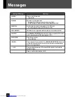
Page 64: ... 29 NOT SUPPORT iPod that is not supported with this device is connected P 34 NonPCM The DIGITAL IN OPTICAL terminal on the rear panel of the main unit is receiving non PCM input signals P 11 TRAY OPEN The CD tray is open RClose the tray UNLOCK The component connected to the DIGITAL IN OPTICAL terminal on the rear panel of the main unit is not turned on Alternatively there is no signal input kHz T...

Page 65: ...s no sound from D IN Check all connections as described in Connecting the System Check whether PCM is selected for the digital audio output setting on the connected component z z 11 No sound from one of the speakers Check all connections as described in Connecting the System Check the volume balance for the left and right speakers z z 8 52 The clock display is flashing Set the clock as described i...

Page 66: ...displayed correctly Refer to Supported Audio Files to check which TAG information can be displayed on this system z 21 iPod iPod cannot be attached firmly Check to see whether the correct Dock adapter is used Then check to see whether the connector between iPod and the system is not damaged and reconnect them z 10 iPod does not provide sound iPod is not properly connected Remove iPod from the syst...

Page 67: ...he AC wall outlet 2Plug the power cord back in while holding down the power key on the main unit 3Upon the start of the microcomputer resetting the display shown on the right appears During the resetting of microcomputer the display goes out z 4When finish resetting it turns to Standby Mode Bear in mind that resetting erases any stored information and restores the system s default settings z Sympt...

Page 68: ...tes of data compression by discarding data not readily audible to humans MP3 can compress data down to rates of approximately 1 11 128 kbps while retaining sound quality equivalent to a music CD 21 Sampling frequency A value that indicates the number of times per second analog signals are sampled for conversion to digital signals The sampling frequency for music CDs is 44 1 kHz Normally the higher...

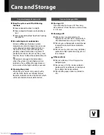
Page 69: ... is present Cleaning the system When the system gets dirty wipe it with a soft dry cloth Never use lacquer thinner benzine alcohol or contact revitalizer which will cause discoloration or deformation z z z Care and storage of CDs Storing a CD If you do not plan to use a CD for a long time remove it from the main unit and store it in its case Cleaning a CD When a disc is contaminated with fingerpri...

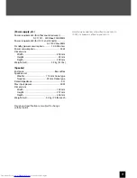
Page 70: ...ut terminals Level Impedance SUB WOOFER PRE OUT 1 V 10 kΩ Speakers Impedance 4 Ω 16 Ω Digital unit Sampling frequencies 32 kHz 44 1 kHz 48 kHz 88 2 kHz 96 kHz Digital input terminals Sensitivity Wave length Optical 15dBm 24dBm 660nm 30nm Output terminals Level Wave length Optical 21 dBm 15 dBm 660 nm Main unit USB Usable USB device USB Mass storage class Interface USB2 0 Full speed USB1 1 compatib...

Page 71: ...10 V 240V 50Hz 60Hz Power requirement for U S A and Canada AC 120 V 60Hz Standby power consumption 1 00 W or less Power consumption 35 W Dimensions Width 200 mm Height 95 mm Depth 299 mm Weight net 2 3 kg 5 1 lbs Speaker Enclosure Bass reflex Speaker unit Woofer 110 mm Cone type Tweeter 25 mm Dome type Rated impedance 4 Ω Max input power 40 W Dimensions Width 140 mm Height 237 mm Depth 236 mm Weig...

Page 72: ...EN 2010 Victor Company of Japan Limited 0410WMKMDWJMM UX J51 MICRO COMPONENT SYSTEM ...

Page 73: ... firmly once inside the cutout of the core filter as shown in the illustration NOTE 1 core filter for each cord Faites passer le cordon à travers le tore de ferrite et enroulez le solidement une fois à l intérieur du creux du tore de ferrite comme montré sur l illustration REMARQUE Un tore de ferrite pour chaque cordon Close the core filter until it clicks shut Refermez le tore de ferrite jusqu à ...

Page 74: ... PLACE STAMP HERE PRODUCT REGISTRATION CARD I QUESTIONNAIRE USA CUSTOMERS ONLY Registering your product will allow us to contact you in the unlikely event a product safety notification is required This form is for Product Registration purposes only Failure to return this form does not diminish your rights during the warranty period THANK YOU FOR PURCHASING THIS JVC PRODUCT REGISTER ONLINE AT REGIS...

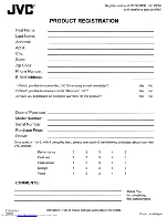
Page 75: ...purchased an extended warranty for this product Date of Purchase Model Number Serial Number Purchase Price Dealer Yes No Yes No Yes No On a scale of 1 to 5 with 5 being the best please rate each of the following attributes about your new JVC product Performance Features Ease of use Design Value COMMENTS 1 1 1 1 1 2 2 2 2 2 3 3 3 3 3 4 4 4 4 4 5 5 5 5 5 Thank You for completing this questionnare 8T...

Page 76: ...9 Do not defeat the safety purpose of the polarized or grounding type plug A polarized plug has two blades with one wider than the other A grounding type plug has two blades and a third grounding prong The wide blade or the third prong are provided for your safety If the provided plug does not fit into your outlet consult an electrician for replacement of the obsolete outlet 10 Protect the power c...

Page 77: ... cause harmful interference to radio communications However there is no guarantee that interference will not occur in a particular installation If this equipment does cause harmful interference to radio or television reception which can be determined by turning the equipment off and on the user is encouraged to try to correct the interference by one or more of the follOWing measures Reorient or re...

Page 78: ...PRODUIT LASER CLASSE 1 2 ATTENTION N ouvrez pas Ie couvercle superieur ni Ie coffret de l appareil lI n y a aucune piece reparable par I utilisateur 11 I interieur de I appareil confiez toute reparation 11 un personnel qualifie 3 ATTENTION Pour les Etats Unis Radiation laser de c1asse II visibles et ou invisible si I appareil est ouvert Ne regardez pas Ie rayon Pour Ie Canada Rayonnement laser vis...

Page 79: ...duit JVC doit etre apporte pour service to an authorized JVC Service Centre service chez un centre de service JVC autorise 2 Limitation This Warranty shall not apply to a Repair or replacement of any cabinets batteries plates connection cords anten nas dust covers knobs speaker grills speaker cones projection screens projection screen savers and all accessories b Any defects caused or repairs requ...

Page 80: ... work manship 4 Exclusion of All Other Express Warranties This warranty constitutes the entire express warranty given by JVC for JVC products and no dealer or service centre personnel or his its or their agent or employee is or are autho rized to extend or enlarge this warranty on be half of JVC 5 Disclaimer of Consequential Damage To the extent the law permits JVC disclaims any responsibility for...

Page 81: ...CATE A JVC SERVICE CENTER LIKE TO PURCHASE ACCESSORIES JVC IS HERE TO HELP TOLL FREE 1 800 252 5722 http www jvc com Remember to retain your Bill of Sale for Warranty Service Do not attempt to service the product yourself Caution To prevent electrical shock do not open the cabinet There are no user serviceable parts inside Please refer to qualified service personnel for repairs BT 51 018 6 1008 ...

Page 82: ...other than a service facility authorized by JVC to render such service or if affixed to any attachment not provided with the products or if the model or serial number has been altered tampered with defaced or removed 2 Initial installation installation and removal from cabinets or mounting systems 3 Operational adjustments covered in the Owner s Manual normal maintenance video and audio head clean...

Reviews: