(No.HC034<Rev.001>)1-13
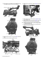
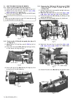
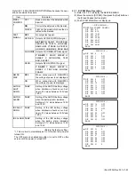
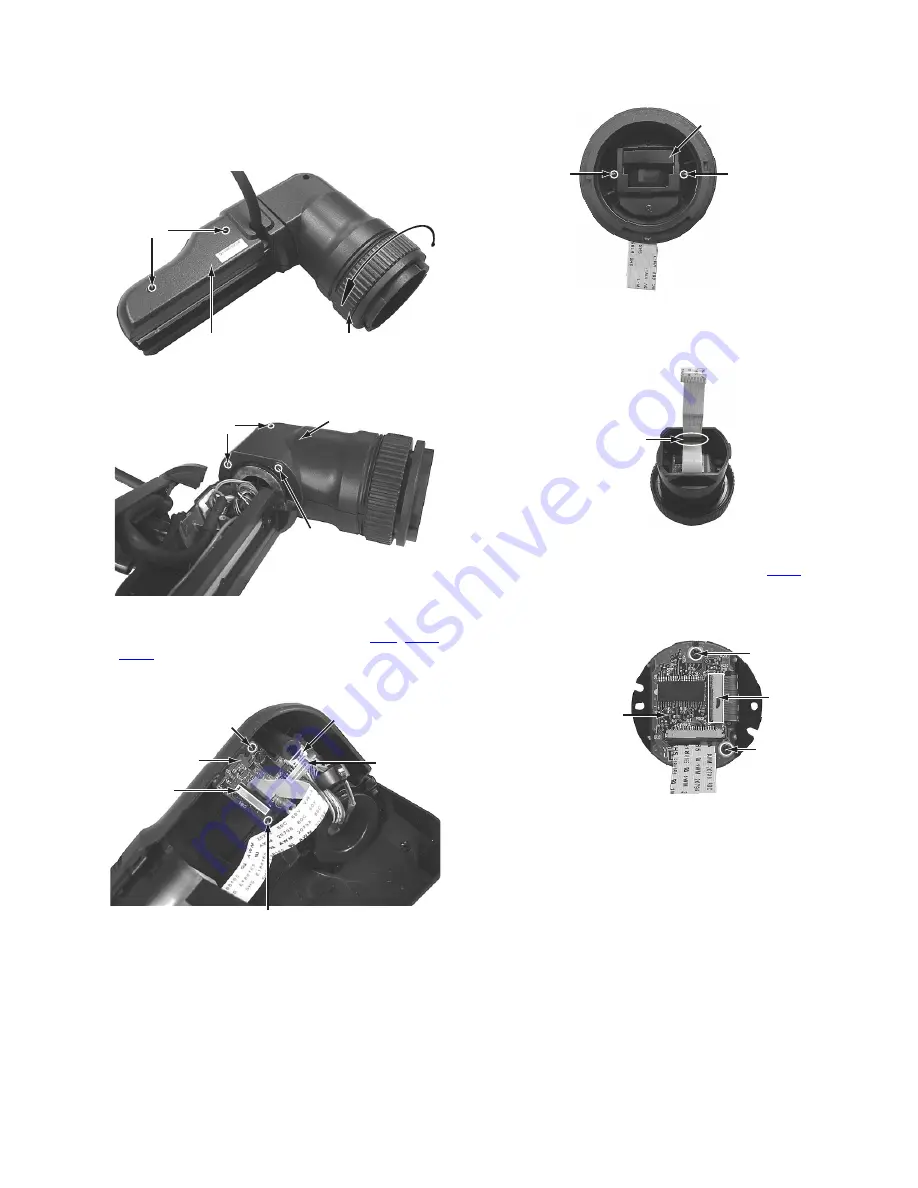
3.6.2 Removing the VF1 board and VF2 board (See figure
39, figure 40, figure 41, figure 42, figure 43 and figure
44)
(1) Remove the lens unit assembly (Refer to the 3.6.1).
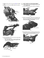
(2) Remove the two screws
(S1)
attaching the VF case B.
(3) Remove the lock ring.
Fig.39
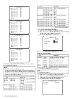
(4) Remove the three screws
C
attaching the VF cover B.
Fig.40
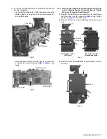
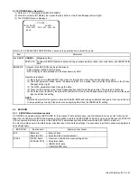
(5) Disconnect the wires from the connectors
CN8
,
CN60
and
CN65
on the VF2 board.
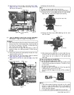
(6) Remove the two screws
(S12)
attaching the VF2 board,
then remove the VF2 board.
Fig.41
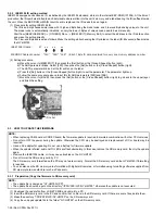
(7) Remove the two screws
D
attaching the LCD module unit,
then remove the LCD module unit.
Fig.42
• To attach the LCD module unit, put the wire through the
slit.
Fig.43
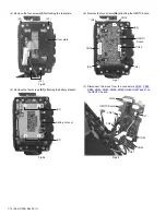
(8) Disconnect the FPC from the connector
CN61
on the VF1
board.
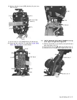
(9) Remove the two screws
(S12)
attaching the VF1 board,
then remove the VF1 board.
Fig.44
Lock ring
VF Case B
(S1)
C
VF Cover B
C
(S12)
(S12)
VF2 Board
CN60
CN8
CN65
LCD Module unit
D
D
Slit
(S12)
CN61
VF1 Board
(S12)


