1-16 (No.HC034<Rev.001>)
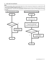
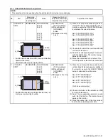
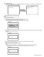
(*1)Do not push the set button because the data of SSE adjustment are reset. In this case, the replacement of the OP block
is needed.
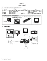
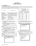
4.3.2 Switches and Functions Used in Adjustments
Most of the adjustment items employ microcomputer-controlled adjustments using electric potentiometers. The adjustment data is
stored in EEPROM.
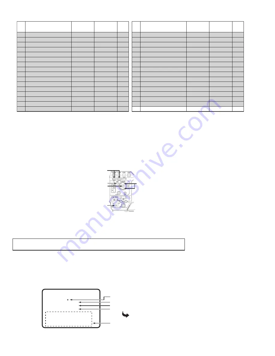
The switches used in the adjustments and their functions are as follows.
[MENU] Button
: Press to start from the adjustment menu.
[USER 1], [USER 2] Button
: Press to select the adjustment item.
[Cross-Shaped] (UP/DOWN) Button : Press UP/DOWN to adjust the selected item.
[Set] Button
: Press to start an adjustment and store the adjustment value in memory.
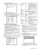
4.3.3 Procedure
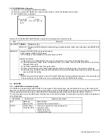
(1) Turn the power ON, while holding the [USER 1] and [USER 2] buttons.
(2) When the power is ON, press the [MENU] button to display the ADJUST MENU.
(3) Push the [Set] button so that " * " lighting, and the [Cross-Shaped] (UP/DOWN) button to the specified value while observing the
designated TP and measuring instrument.
(4) After completing the adjustment, push the [Set] button to delete the "*" and store the adjustment value in memory.
(5) Press the [USER 1] and [USER 2] button to select the next item to adjust.
(6) Adjust for each item to do same procedure as above (3)(4).
(7) After completing all adjustments, turn the power OFF and ON again.
(8) To return to normal operation mode, turn the power OFF and ON again.(If did not re-start camera power, camera will be still in
ADJUST MODE, so if press the [MENU] button then ADJUST MENU indicate on the screen and will not indicate normal menu
screen.)
4.3.4 Adjustment mode
* When the adjustment item is selected, the input signal, internal mode and output signal flow are automatically set as specified.
235
236
237
238
239
240
427
351
241
242
243
244
245
246
247
248
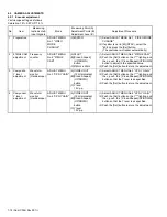
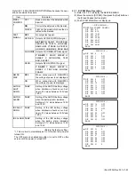
RESET START[B]R
RESET STOP[B]R
SHP PHASE[B]R
SHD PHASE[B]R
AD OUT PHASE[B]R
LVDS CLK[B]R
AFE CLAMP[B]R
AFE TEST MODE
H1 START[R]
H1 STOP[R]
H2 START[R]
H2 STOP[R]
H1L START[R]L
H1L STOP[R]L
RESET START[R]L
RESET STOP[R]L
0 to 63
0 to 63
0 to 63
0 to 63
0 to 31
0 to 15
-128 to 127
128
0 to 63
0 to 63
0 to 63
0 to 63
0 to 63
0 to 63
0 to 63
0 to 63
60, 50, 48, 40
60, 50, 48, 40
60, 50, 48, 40
60, 50, 48, 40
60, 50, 48, 40
60, 50, 48, 40
60, 50, 48, 40
60, 50, 48, 40
60, 50, 48, 40
60, 50, 48, 40
60, 50, 48, 40
60, 50, 48, 40
60, 50, 48, 40
60, 50, 48, 40
60, 50, 48, 40
60, 50, 48, 40
112
113
114
115
116
117
118
119
120
121
122
123
124
125
126
127
Adj
No.
Adjustment item
Mode
Display
order
Adjustment
range
249
250
251
252
428
253
254
255
256
257
258
259
260
429
351
201
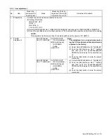
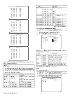
SHP PHASE[R]L
SHD PHASE[R]L
AD OUT PHASE[R]L
LVDS CLK[R]L
AFE CLAMP[R]L
H1L START[R]R
H1L STOP[R]R
RESET START[R]R
RESET STOP[R]R
SHP PHASE[R]R
SHD PHASE[R]R
AD OUT PHASE[R]R
LVDS CLK[R]R
AFE CLAMP[R]R
AFE TEST
EEP COPY SYS TO CAM
0 to 63
0 to 63
0 to 31
0 to 15
-128 to 127
0 to 63
0 to 63
0 to 63
0 to 63
0 to 63
0 to 63
0 to 31
0 to 15
-128 to 127
-
-
60, 50, 48, 40
60, 50, 48, 40
60, 50, 48, 40
60, 50, 48, 40
60, 50, 48, 40
60, 50, 48, 40
60, 50, 48, 40
60, 50, 48, 40
60, 50, 48, 40
60, 50, 48, 40
60, 50, 48, 40
60, 50, 48, 40
60, 50, 48, 40
60, 50, 48, 40
60, 50, 48, 40
60, 50, 48, 40
128
129
130
131
132
133
134
135
136
137
138
139
140
141
142
143
Adj
No.
Adjustment item
Mode
Display
order
Adjustment
range
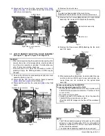
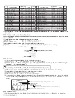
USER 1, USER 2 Button
MENU Button
Set Button
POWER Switch
Cross-Shaped
(UP/DOWN) Button
Note:
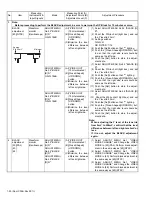
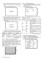
Do not turn the power off while "*" is blinking. Because all adjustment data may be broken.
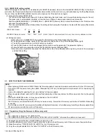
--- ADJUST [60] ---
26. IN GAIN [B]
VR DATA
:- 12
CTL OUT : 77
SET DATA :- 12
R
G
B
L-R X
X X
REF.L XXX XXX XXX
REF.R XXX XXX XXX
Potentiometer value
D/A output value
Adjustment value currently set
Displayed as the adjustment menu items.
The value changes when the potentiometer value is stored in memory.
Usually not displayed. Starts lighting when the [Set] button is pushed.


