background image

(No.HC034<Rev.001>)1-3

SECTION 1

PRECAUTION

1.1

SAFETY PRECAUTIONS

Prior to shipment from the factory, JVC products are strictly in-

spected to conform with the recognized product safety and elec-
trical codes of the countries in which they are to be

sold.However,in order to maintain such compliance, it is equally

important to implement the following precautions when a set is
being serviced.

1.1.1 Precautions during Servicing

(1) Locations requiring special caution are denoted by labels

and inscriptions on the cabinet, chassis and certain parts of

the product.When performing service, be sure to read and
comply with these and other cautionary notices appearing

in the operation and service manuals.

(2) Parts identified by the  symbol and shaded ( 

 ) parts

are critical for safety.

Replace only with specified part numbers.

NOTE :

Parts in this category also include those specified to

comply with X-ray emission standards for products
using cathode ray tubes and those specified for

compliance with various regulations regarding spu-

rious radiation emission.

(3) Fuse replacement caution notice.

Caution for continued protection against fire hazard.

Replace only with same type and rated fuse(s) as speci-
fied.

(4) Use specified internal wiring. Note especially:

• Wires covered with PVC tubing
• Double insulated wires

• High voltage leads

(5) Use specified insulating materials for hazardous live parts.

Note especially:

• Insulation Tape

• PVC tubing
• Spacers

• Insulation sheets for transistors

• Barrier

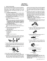
(6) When replacing AC primary side components (transformers,

power cords, noise blocking capacitors, etc.) wrap ends of

wires securely about the terminals before soldering.

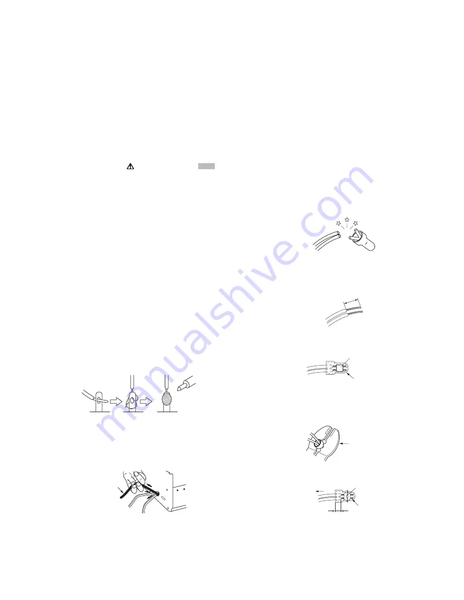
Fig.1-1-1

(7) Observe that wires do not contact heat producing parts

(heatsinks, oxide metal film resistors, fusible resistors, etc.)

(8) Check that replaced wires do not contact sharp edged or

pointed parts.

(9) When a power cord has been replaced, check that 10-15

kg of force in any direction will not loosen it.

Fig.1-1-2

(10) Also check areas surrounding repaired locations.
(11) Products using cathode ray tubes (CRTs) In regard to such

products, the cathode ray tubes themselves, the high volt-

age circuits, and related circuits are specified for compli-
ance with recognized codes pertaining to X-ray emission.

Consequently, when servicing these products, replace the

cathode ray tubes and other parts with only the specified

parts. Under no circumstances attempt to modify these cir-
cuits.Unauthorized modification can increase the high volt-

age value and cause X-ray emission from the cathode ray

tube.

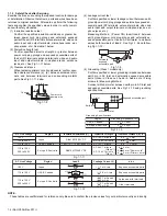
(12) Crimp type wire connector In such cases as when replac-

ing the power transformer in sets where the connections

between the power cord and power trans former primary
lead wires are performed using crimp type connectors, if

replacing the connectors is unavoidable, in order to prevent

safety hazards, perform carefully and precisely according
to the following steps.

Connector part number

 :E03830-001

Required tool

 : Connector crimping tool of the proper

type which will not damage insulated parts.

Replacement procedure

a) Remove the old connector by cutting the wires at a

point close to the connector.Important : Do not re-

use a connector (discard it).

Fig.1-1-3

b) Strip about 15 mm of the insulation from the ends

of the wires. If the wires are stranded, twist the

strands to avoid frayed conductors.

Fig.1-1-4

c) Align the lengths of the wires to be connected. In-

sert the wires fully into the connector.

Fig.1-1-5

d) As shown in Fig.1-1-6, use the crimping tool to

crimp the metal sleeve at the center position. Be

sure to crimp fully to the complete closure of the
tool.

Fig.1-1-6

e) Check the four points noted in Fig.1-1-7.

Fig.1-1-7

(13)

Battery replacement caution notice.
CAUTION RISK OF EXPLOSION IF BATTERY IS RE-
PLACED BY AN INCORRECT TYPE. 
DISPOSE OF USED BATTERIES ACCORDING TO THE
INSTRUCTIONS.

Power cord

cut close to connector

15 mm

Connector

Metal sleeve

1.2

5

2.0

5.5

Crimping tool

Not easily pulled free

Crimped at approx. center

of metal sleeve

Conductors extended

Wire insulation recessed

more than 4 mm

Summary of Contents for GY-HM790U

Page 1: ...2 HOW TO REMOVE THE EXTERIOR PARTS 1 5 3 3 HOW TO REMOVE THE OPTICAL BLOCK ASSEMBLY 1 7 3 4 HOW TO REMOVE THE MAJOR BOARDS 1 8 3 5 HOW TO REMOVE THE HANDLE ASSEMBLY 1 11 3 6 HOW TO REMOVE THE VIEW FINDER ASSEMBLY 1 12 4 ADJUSTMENT 1 14 4 1 FUNCTIONS REQUIRED FOR ADJUSTMENTS SETUP 1 14 4 2 STANDARD SETUP 1 14 4 3 ADJUSTMENT MENU 1 15 4 4 FLOWCHART OF ADJUSTMENTS 1 17 4 5 CAMERA ADJUSTMENTS 1 18 5 T...

Page 2: ... unbalanced HD SDI Compliant with SMPTE 292 M SD SDI Compliant with SMPTE 259 M AUDIO INPUT 1 2 terminal MIC 60 dBu 3k Ω XLR balanced 48 V output phantom power supply LINE 4 dBu 10k Ω XLR balanced AUDIO OUTPUT terminal 8 1 dBu when audio signal process output is 20 dB 1 k Ω RCA x2 unbalanced PHONES terminal 3 5 mm mini jack stereo x 2 REMOTE terminal 6 pin JVC remote control connection IEEE1394 te...

Page 3: ...rection will not loosen it Fig 1 1 2 10 Also check areas surrounding repaired locations 11 Products using cathode ray tubes CRTs In regard to such products the cathode ray tubes themselves the high volt age circuits and related circuits are specified for compli ance with recognized codes pertaining to X ray emission Consequently when servicing these products replace the cathode ray tubes and other...

Page 4: ...rd plug prongs and externally ex posed accessible parts Use an AC voltmeter to measure across both terminals of load Z See Fig 1 1 9 and follow ing Fig 1 1 12 Fig 1 1 9 5 Grounding Class 1 model only Confirm specified or lower grounding impedance between earth pin in AC inlet and externally exposed accessible parts Video in Video out Audio in Audio out or Fixing screw etc Measuring Method Connect ...

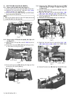
Page 5: ...following table 3 2 HOW TO REMOVE THE EXTERIOR PARTS 3 2 1 Removing the left side cover assembly See figure 1 figure 2 figure 3 figure 4 figure 5 figure 6 and figure 7 1 Remove the two screws S10 attaching the shoulder pad then remove the shoulder pad 2 Remove the one screw S1 attaching the CN cover as sembly Fig 1 Fig 2 Fig 3 Symbol Design Part No Color S1 QYSPSPU2040MA Black S2 QYSPSPU2080MA Bla...

Page 6: ...m the connectors CN34 and CN13 on the CODEC board 8 Disconnect the wire from the connector CN43 on the LINE SEL board then remove the left side cover assembly 3 2 2 Removing the right side cover assembly See figure 8 figure 9 and figure 10 1 Remove the five screws S1 and two screws S11 attach ing the right side cover assembly Fig 8 Fig 9 Left side cover assembly S2 S1 S2 S2 S1 S11 S11 CODEC Board ...

Page 7: ...e not to damage cables also the position ing of the wire assembly is important A malfunction may occur if wires are somehow caught up Take also care not to press the IS boards or cables If pressing strongly the RGB registration of CCDs may be changed AUDIO Board Right side cover assembly CN24 CN11 CN14 CN43 Optical block assembly CN90 CN28 CN26 CAM Board CN27 Note The glue has been applied to the ...

Page 8: ...figure 18 figure 19 figure 20 figure 21 and figure 22 1 Remove the left side cover assembly and right side cover assembly Refer to the 3 2 2 Disconnect the wires from the connectors CN26 CN27 CN28 CN90 CN8 CN29 and CN30 on the CAM board 3 Remove the two screws S7 attaching the SDI board then remove the SDI board 4 Remove the six screws S6 attaching the CAM board Fig 18 5 Disconnect the wires from ...

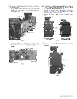
Page 9: ...NTC board and REG board See fig ure 23 figure 24 figure 25 figure 26 figure 27 figure 28 figure 29 figure 30 and figure 31 1 Remove the right side cover assembly and then discon nect the wires from the connector CN88 on the CODEC board and CN29 on the CAM board 2 Remove the four screws A attaching the battery mount unit Fig 23 3 Remove the four screws B attaching the bracket For only E model Fig 2...

Page 10: ...ttery bracket Fig 26 6 Remove the four screws S6 attaching the GENTC board Fig 27 7 Disconnect the wires from the connectors CN58 CN78 CN59 CN32 CN67 CN56 CN92 CN69 CN57 and J1 on the GENTC board Fig 28 S1 S1 S1 Rear plate S7 S7 Battery bracket S6 S6 CN78 CN58 CN59 GENTC Board S6 S6 CN57 CN69 CN92 J1 CN32 GENTC Board CN67 CN56 ...

Page 11: ... Fig 30 Fig 31 3 5 HOW TO REMOVE THE HANDLE ASSEMBLY See fig ure 32 figure 33 figure 34 and figure 35 1 Remove the left side cover assembly and right side cover assembly Refer to the 3 2 2 Remove the two screws S5 attaching the handle cover T 3 Remove the one screw S1 attaching the handle cover R Fig 32 S13 S13 S13 S13 Rear main base assembly S6 CN30 S6 REG Board CN109 S6 S6 CN32 CN31 REG Board CN...

Page 12: ...ing the lens unit assembly See figure 36 fig ure 37 and figure 38 1 Loosen the lock ring then pull out the lens unit assembly Fig 36 2 Insert a fine screwdriver into the hole on the back of the slide cover While keeping the fine screwdriver inserted turn the lens unit assembly to the direction of the arrow The lens unit assembly can be removed Fig 37 3 When attaching the lens unit assembly align t...

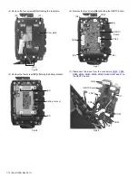
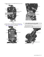
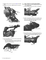
Page 13: ... connectors CN8 CN60 and CN65 on the VF2 board 6 Remove the two screws S12 attaching the VF2 board then remove the VF2 board Fig 41 7 Remove the two screws D attaching the LCD module unit then remove the LCD module unit Fig 42 To attach the LCD module unit put the wire through the slit Fig 43 8 Disconnect the FPC from the connector CN61 on the VF1 board 9 Remove the two screws S12 attaching the VF...

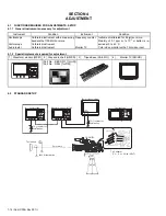
Page 14: ... Calibrated instrument Frequency counter Monitor TV Instrument calibrated for 8 digits or more Stability of 0 1 ppm or 1x10 7 or better is re quired at 0 to 40 C Color video monitor with a 75Ω video input 1 Waveform monitor WFM 2 Gray scale chart HD SD 3 Tripod base KA 551U 4 Monitor TV SD HD Part No RESC 017 for HD Part No GS2L for SD Vectorscope 75 resistor for termination 75 resistor for termin...

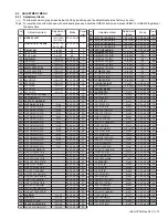
Page 15: ... 60 50 48 40 60 50 48 40 60 50 48 40 1 2 3 4 5 6 7 8 9 10 11 12 13 14 15 16 17 18 19 20 21 22 23 24 25 26 27 28 29 30 31 32 33 34 35 36 37 38 39 40 41 42 43 44 45 46 47 48 49 50 51 52 53 54 55 Adj No Adjustment item Mode Display order Adjustment range 45 46 47 48 353 412 413 414 415 416 417 420 421 422 423 7 13 200 201 202 203 204 205 206 207 208 209 210 211 212 424 213 214 215 216 217 218 219 220...

Page 16: ...4 245 246 247 248 RESET START B R RESET STOP B R SHP PHASE B R SHD PHASE B R AD OUT PHASE B R LVDS CLK B R AFE CLAMP B R AFE TEST MODE H1 START R H1 STOP R H2 START R H2 STOP R H1L START R L H1L STOP R L RESET START R L RESET STOP R L 0 to 63 0 to 63 0 to 63 0 to 63 0 to 31 0 to 15 128 to 127 128 0 to 63 0 to 63 0 to 63 0 to 63 0 to 63 0 to 63 0 to 63 0 to 63 60 50 48 40 60 50 48 40 60 50 48 40 60...

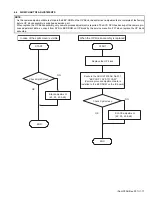
Page 17: ...he SYS CPU has backup of the camera pro cess adjustment data so copy it from SYS to EEP ROM on OP block by the service menu No 201 when replace the OP block assembly START END OK NG START END OK NG Check Split Screen Replace the OP block Execute the ADJUST MENU No 201 EEP COPY SYS TO CAM Camera process adjustment data is installed to the EEP ROM on the IS board Check Split screen BLACK adjustment ...

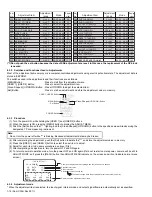
Page 18: ...nd then push the Cross Shaped UP DOWN button to adjust to the specified value 3 Push the Set button to store the adjustment 3 Composite Y level adjustment Waveform monitor Oscilloscope ADJUST MENU No 3 CPS Y GAIN A Y VIDEO OUT 75Ω terminated B Cross Shaped UP DOWN button C Y level 1 0Vp p 1 Select ADJUST MENU No 3 CPS Y GAIN 2 Push the Set button so that lighting and then push the Cross Shaped UP ...

Page 19: ...he power of GY HM790 2 FLARE adjustment ADJUST MENU No 40 FLARE B A Y VIDEO OUT 75Ω terminated B Cross Shaped UP DOWN button C DATA 13 Note This adjustment is no required when replac ing the OP block because this adjustment is adjusted in the factory 1 Select ADJUST MENU No 40 FLARE B 2 Push the Set button so that lighting and then push the Cross Shaped UP DOWN button to adjust to the specified va...

Page 20: ...ld be same as the left side 16 Push the Set button to store the adjust ment data Note When adjusting the Y level of the lens iris from 0mV to 200mV confirm that the level difference between left and right are 5mV or less If it is not adjust the BLACK adjustment again ADJUST MENU No 34 BLACK B R GAIN 18dB A Y VIDEO OUT 75Ω terminated B Cross Shaped UP DOWN button C Minimize the level difference bet...

Page 21: ... Set button The marker line ap pears on the monitor 4 Move the marker line to the center of the color strip noise so that the color noise data If white blemish exists on HOB blemish correction operate miss clamp Horizontal noise may be slightly visible 2 VT WHITE SPOT HD MONITOR ADJUST MENU No 420 No 421 No 422 No 423 A Y VIDEO OUT 75Ω terminated B Cross Shaped UP DOWN button C Disappear the strip...

Page 22: ...ED MENU 5 1 2 3 SERVICE MENU Display Service menu 2 1 While holding down the DISPLAY button turn ON the power 2 While holding down the FOCUS ASSIST button and the USER 3 button press the MENU button to display the SERVICE MENU MENU Item Displayed content When power up Holding DISPLAY button Activation method FOCUS ASSIST MENU FOCUS ASSIST USER 3 MENU FIRMWARE Firmware Package version indication YE...

Page 23: ...ble 3 When only recording to the SDHC memory cord this func tion is available 5 1 5 1 White blemish detection 1 Open the User Menu then set Camera Resolution in Record Format to 1280x720 and Frame Bit Rate to 60p HQ or 60p SP 2 Open the ADVANCED FUNCTION Menu change the PIX EL COMPEN DET parameter to EXECUTE and then press the Set button NOTE To cancel the parameter setting change press the CAN CE...

Page 24: ... OUT and then press the Set button or the Cross Shaped button right 2 The SDI OUT Menu is displayed Refer to 5 1 5 ADVANCED FUNCTION Menu because the oper ations are almost the same Bold is the factory setting 5 1 6 SERVICE FUNCTION Menu Operation 1 Refer to 5 1 2 3 to display the SERVICE MENU 2 Move the cursor to SERVICE FUNCTION then press the Set button or the Cross Shaped button right 3 The SE...

Page 25: ...M HP250 the voltage of power is not displayed ON When connecred with RM HP250 the voltage of power is displayed ANTON SHUT DOWN 12 0V Setting of the ANTON battery voltage when shutdown should occur Set ting in 0 1V steps between 12 0V and 14 0V ANTON ALARM 12 8V Setting of the ANTON battery voltage when the battery alarm indicated Setting in 0 1V steps between 12 0V and 14 0V IDX SHUT DOWN 12 0V S...

Page 26: ...SW 8 to 15 OFF Change prohibited DIP SW 5 8 DIP SW 32 OFF DIP SW 33 OFF DIP SW 34 OFF DIP SW 35 OFF DIP SW 36 OFF DIP SW 37 OFF DIP SW 38 OFF DIP SW 39 OFF BACK DIP SW 6 8 DIP SW 40 OFF DIP SW 41 OFF DIP SW 42 OFF DIP SW 43 OFF DIP SW 44 OFF DIP SW 45 OFF DIP SW 46 OFF DIP SW 47 OFF BACK DIP SW 7 8 DIP SW 48 OFF DIP SW 49 OFF DIP SW 50 OFF DIP SW 51 OFF DIP SW 52 OFF DIP SW 53 OFF DIP SW 54 OFF DI...

Page 27: ...all EEP ROM data to default settings except adjustment data hour meter data and IEEE1394 ID data MEM EDIT Contents of the EEP ROM can be edited directly ADR Address 0x000 0x9DF display DATA Display of data embedded in address shown by ADR Operation procedure 1 Move the cursor to MEM EDIT then press the Set button or the Cross Shaped button right 2 The ADR parameter blinks Select the address ADR to...

Page 28: ...he Cross Shaped button right to go back to the upper layer and finish the setting 5 3 HOW TO UPDATE THE FIRMWARE 5 3 1 Preparation Copy the firmware to SD memory card 1 Download the update file from JS NET SMIS and unzip it to a PC 2 Insert the SD memory card to the PC and confirm that no file is in the SD memory card If there are some files delete them 3 Make the directory PRIVATE JVC GY HM790 on...

Page 29: ... AUDIO CH 1 and CH 2 blink slowly It takes about 5 minutes to complete the update Complete is displayed on the LCD display 5 After complete the updating remove the SD memory card The GY HM790 reboots automatically 6 Turn OFF the power and turn it ON again 7 Enter the Service Menu to check the CPU VERSION Note Confirm the firmware in the SD card if the update can t be Executed was displayed on the ...

Page 30: ...ted in OPTICAL BLOCK ASSEMBLY ISB Board OPTICAL BLOCK ASSEMBLY is supplied from the parts center after adjustment of CCD Split Screen Flare ADJ etc is completed By transferring the adjustment data of camera process after changing OP BLOCK ASSEMBLY it is not required to readjust basically When the split screen appear on the monitor TV confirm the 4 5 2 No 3 BLACK adjustment How to transfer the adju...

Page 31: ... No HC034 Rev 001 VSE Printed in Japan Victor Company of Japan Limited Business Solution Division ...

Reviews: