1-6 (No.HC034<Rev.001>)
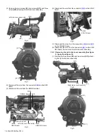
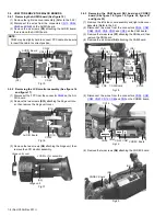
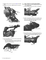
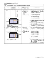
(3) Remove the two screws
(S1)
, two screws
(S11)
and three
screws
(S2)
attaching the left side cover assembly.
Fig.4
Fig.5
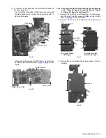
(4) Disconnect the wire from the connector
CN84
on the BNC
board.
(5) Disconnect the wire from the HD/SD terminal.
Fig.6
(6) Disconnect the wire from the connector
CN93
on the ECAP
board.
Fig.7
(7) Disconnect the wires from the connectors
CN34
and
CN13
on the CODEC board.
(8) Disconnect the wire from the connector
CN43
on the LINE
SEL board, then remove the left side cover assembly.
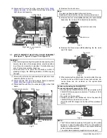
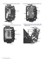
3.2.2 Removing the right side cover assembly (See figure
8, figure 9 and figure 10)
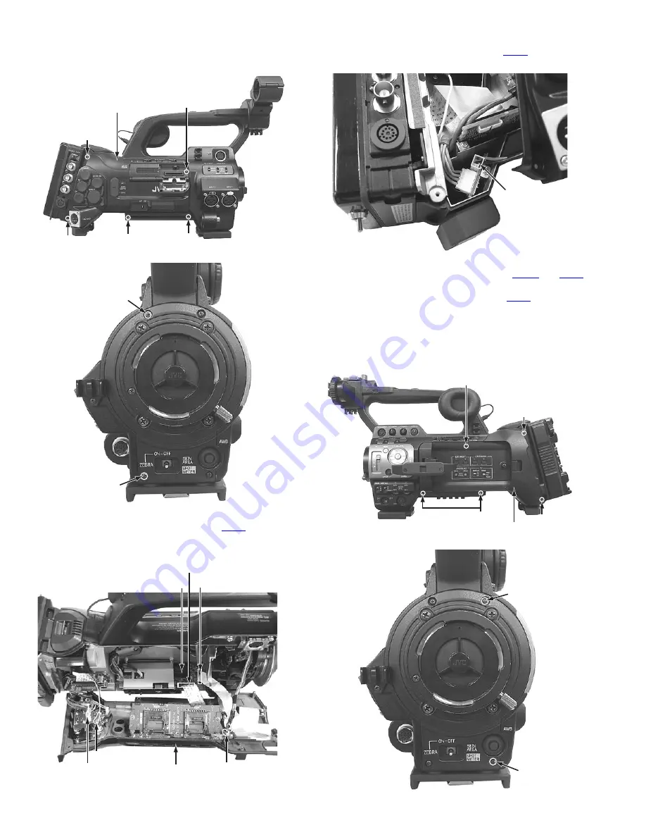
(1) Remove the five screws
(S1)
and two screws
(S11)
attach-
ing the right side cover assembly.
Fig.8
Fig.9
Left side cover assembly
(S2)
(S1)
(S2)
(S2)
(S1)
(S11)
(S11)
CODEC Board
Left side cover assembly
CN34
CN13
HD/SD Terminal
CN43
LINE SEL Board
CN84
BNC Board
CN93
ECAP Board
(S1)
(S1)
(S1)
(S1)
Right side cover assembly
(S11)
(S11)


