(No.HC034<Rev.001>)1-9
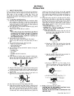
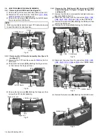
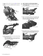
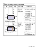
(7) To remove the CAM board and the CODEC board, slide the
two boards together.
• As the CAM board and the CODEC board are connected
board to board, be very careful when removing and at-
taching the boards.
Fig.21
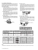
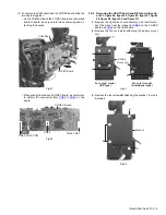
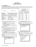
• When placing the removed CODEC board, be careful not
to deform the connectors from
CN89
to
CN94
on the
board.
Fig.22
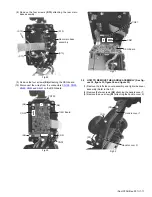
3.4.4 Removing the GENTC board and REG board (See fig-
ure 23, figure 24, figure 25, figure 26, figure 27, figure
28, figure 29, figure 30 and figure 31)
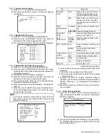
(1) Remove the right side cover assembly, and then discon-
nect the wires from the connector
CN88
on the CODEC
board and
CN29
on the CAM board.
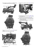
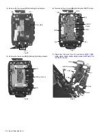
(2) Remove the four screws
A
attaching the battery mount
unit.
Fig.23
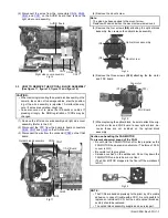
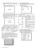
(3) Remove the four screws
B
attaching the bracket. (For only
E model)
Fig.24
CAM Board
CODEC Board
CODEC Board
CN94
CN89,CN90,CN91
CN92,CN93
A
Battery
mount unit
A
A
A
For only E model
(IDX type)
For only U model
(Antonbauer type)
B
B
B
Bracket


