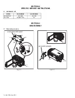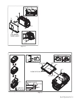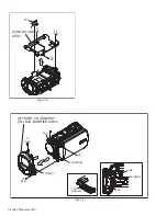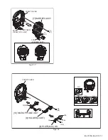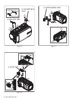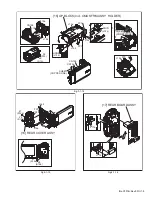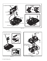
1-18 (No.YF376<Rev.001>)
4.2
JIG CONNECTOR CABLE CONNECTION
4.2.1 Cautions
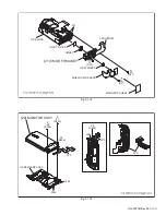
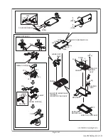
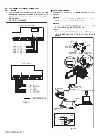
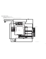
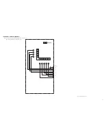
(1) Only 9 of 30pins of JIG CONNECTOR CABLE(PN:YTU93106B)
are extended with wires. Additional 2pins (13 and 28) need
to be soldered and extended with the wires for adjustment
and checking.
See Fig. 4-2-1 for details.
Fig.4-2-1
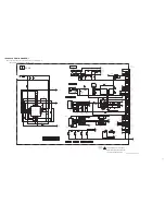
Connection procedure
·
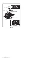
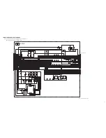
Remove the 2 screws (1-2), and then remove the TOP COV-
ER ASSY.
NOTE1a:
Release or remove the JACK COVER ASSY as it interferes
with the disassembly of TOP COVER ASSY.
NOTE1b:
To remove the TOP COVER ASSY, press [A] indicated with
an arrow, and release the HOOK (L1a) first.
NOTE1c:
When removing the last HOOK (L1e), be careful not to de-
form or apply excess force to the parts to avoid possible
damage.
Fig.4-2-2
: ADDITIONAL WIRE
13
22pin NOT USED
23pin NOT USED
26pin NOT USED
28pin IF_RX
29pin AL_2.83V
8pin NOT USED
9pin GND
5pin NOT USED
13pin IF_TX
12pin NOT USED
10pin GND
28
<COMPONENT SIDE>
<FOIL SIDE>
10
1
20
11
PC CABLE
JIG CONNECTOR
JIG CONN.
COMMUNICATION
CABLE
JIG CONNECTOR
CABLE
CONVERSION
CONNECTOR
MENU
RS232C
COM PORT
SERVICE SUPPORT SYSTEM
PERSONAL COMPUTER
COMMUNICATION
CABLE
JIG CONNECTOR
BLUE
RED
WHITE
BLACK
TO AL_2.83V
TO IF_RX
TO IF_TX
TO GND
(MAIN CN110)
JACK COVER
ASSY
NOTE1a
NOTE1b
NOTE1c
1
(S1)
L1a
L1e
L1d
L1c
[1]
[A]
L1b
2
(S1)
or

