1-14 (No.YA409)
3.1.2 REAR SIDE DISASSEMBLY
3.1.2.1
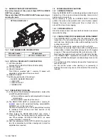
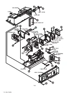
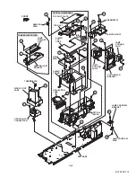
REMOVING THE LAMP UNIT (Fig.3)
(1) Remove the 1 screw
[A]
.
(2) Remove the LAMP COVER.
(3) Remove the 2 screws
[B]
(4) Pull out the LAMP UNIT.
NOTE :
• Do not leave the LAMP COVER removed for long time to
prevent dirt and dust form covering the lens.
• Make sure that the LAMP COVER is completely installed.
3.1.2.2
REMOVING THE BODY COVER (Fig.3)
(1) Remove the 9 screws
[C]
.
(2) Remove the 5 screws
[E]
.
(3) Remove the BODY COVER.
NOTE :
• Do not leave the BODY COVER removed for long time to
prevent soiling from dust.
3.1.2.3
REMOVING THE MAIN UNIT (Fig.3)
• Remove the LAMP COVER.
• Remove the BODY COVER.
(1) Remove the 4 screws
[F]
(2) Remove the BODY BRACKET.
(3) Remove the 2 screws
[G]
(4) The MAIN UNIT is pulled out to the back side.
CAUTION :
•
Except for confirmation of projection images on the
screen and audio output through the speakers, the
removed MAIN UNIT is still workable in the same state
as if it is still built-in the TV set. Therefore, the MAIN
UNIT can be removed, if necessary, for board diagnosis,
electric testing, etc. apart from confirmation of screen
images and audio output. Do not leave the MAIN UNIT
removed for long time to prevent soiling from dust.
•
Because of the large size, at least 2 persons are
recommended for removal and reassemble.
•
When carrying the MAIN UNIT, use care not to drop,
shock or shake it.
•
Do not stain or damage the projection lens.
•
Do not look directly at the light during service.
•
Do not touch the lamp directly as it presents a burn
hazard.
NOTE :
• When not performing repair work, attach the cap on the lens
to preventing dust from covering.
• When mounting to the set, make sure the front of the lens is
in contact with the cushion on the set (body) side.
• Make sure that FRONT LED PWB connector is completely
connect to the ANALOG PWB connector.
• When wire clamps are removed during work, use care to
restore them precisely to their original positions.
Performance can be affected if these are not returned to the
original positions.
3.1.2.4
REMOVING THE AV TERMINAL BOARD (Fig.3)
• Remove the LAMP COVER.
• Remove the BODY COVER.
• Remove the BODY BRACKET.
• Remove the MAIN UNIT.
(1) Remove the 3 screws
[H]
, 3 screws
[J]
and the 8 screws
[K]
.
(2) Remove the 2 hex screws
[L]
.
(3) Remove the nut attaching the ANTENNA TERMINAL.
(4) Remove the AV TERMINAL BOARD.
3.1.2.5
REMOVING THE POWER PWB (Fig.3)
• Remove the LAMP COVER.
• Remove the BODY COVER.
• Remove the BODY BRACKET.
• Remove the MAIN UNIT.
(1) Remove the POWER CORD.
(2) Remove the 7 screws
[M]
.
(3) Remove the POWER PWB.
3.1.2.6
REMOVING THE TUNER PWB (Fig.3)
• Remove the LAMP COVER.
• Remove the BODY COVER.
• Remove the BODY BRACKET.
• Remove the MAIN UNIT.
• Remove the AV TERMINAL BOARD.
(1) Remove the 1 screw
[N]
.
(2) Remove the HANGER BRACKET with TUNER PWB.
(3) Remove the 3 screws
[P]
.
(4) Remove the TUNER PWB.
3.1.2.7
REMOVING THE ANALOG PWB (Fig.3)
• Remove the LAMP COVER.
• Remove the BODY COVER.
• Remove the BODY BRACKET.
• Remove the MAIN UNIT.
• Remove the AV TERMINAL BOARD.
• Remove the POWER PWB and TUNER PWB.
(1) Remove the 4 screws
[Q]
.
(2) Remove the ANALOG PWB.


