(No.YA409)1-17
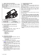
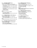
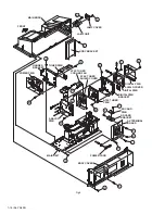
3.1.2.12 REMOVING THE LAMP COVER SW PWB (Fig.4)
• Remove the LAMP COVER.
• Remove the BODY COVER.
• Remove the BODY BRACKET.
• Remove the MAIN UNIT.
(1) Remove the 2 screws
[A]
.
(2) Remove the LAMP COVER SW BRACKET with LAMP
COVER SW PWB.
(3) Remove the 1 screw
[B]
.
(4) Remove the LAMP COVER SW PWB.
3.1.2.13 REMOVING THE TERMOSTAT (Fig.4)
• Remove the LAMP COVER.
• Remove the BODY COVER.
• Remove the BODY BRACKET.
• Remove the MAIN UNIT.
(1) Remove the 2 screws
[C]
.
(2) Remove the THERMOSTAT.
3.1.2.14 REMOVING THE LAMP FAN DUCT (Fig.4)
• Remove the LAMP COVER.
• Remove the BODY COVER.
• Remove the BODY BRACKET.
• Remove the MAIN UNIT.
• Remove the THERMOSTAT.
(1) Remove the 5 screws
[D]
.
(2) Remove the LAMP FAN DUCT.
3.1.2.15 REMOVING THE LAMP COOLING FAN -1 (Fig.4)
• Remove the LAMP COVER.
• Remove the BODY COVER.
• Remove the BODY BRACKET.
• Remove the MAIN UNIT.
• Remove the LAMP FAN DUCT.
(1) Remove the 2 screws
[E]
.
(2) Remove the COOLING FAN BRACKET by pulling
transversally.
(3) Remove the 2 screws
[F]
.
(4) Remove the LAMP COOLING FAN-1.
3.1.2.16 REMOVING THE LAMP COOLING FAN -2 (Fig.4)
• Remove the LAMP COVER.
• Remove the BODY COVER.
• Remove the BODY BRACKET.
• Remove the MAIN UNIT.
• Remove the LAMP FAN DUCT.
• Remove the COOLING FAN BRACKET.
(1) Remove the 2 screws
[G]
.
(2) Remove the LAMP COOLING FAN -2.
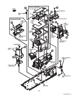
3.1.2.17 REMOVING THE LAMP BALLAST BLOCK (Fig.4)
• Remove the LAMP COVER.
• Remove the BODY COVER.
• Remove the BODY BRACKET.
• Remove the MAIN UNIT.
(1) Remove the 2 screws
[H]
.
(2) Remove the LAMP BALLAST UNIT.
(3) Remove the 1 screw
[J]
.
(4) Remove the LAMP BALLAST BRACKET.
3.1.2.18 REMOVING THE IRIS PWB (Fig.4)
• Remove the LAMP COVER.
• Remove the BODY COVER.
• Remove the BODY BRACKET.
• Remove the MAIN UNIT.
(1) Remove the 2 screws
[K]
.
(2) Remove the IRIS PWB.
3.1.2.19 REMOVING THE REMOCON PWB(Fig.4)
• Remove the LAMP COVER.
• Remove the BODY COVER.
• Remove the BODY BRACKET.
• Remove the MAIN UNIT.
(1) Remove the 1 screw
[L]
.
(2) Remove the REMOCON PWB.
3.1.2.20 REMOVING THE OPTICAL / DRIVE ASS'Y (Fig.4)
• Remove the LAMP COVER.
• Remove the BODY COVER.
• Remove the BODY BRACKET.
• Remove the MAIN UNIT.
• Remove the LAMP FAN DUCT.
(1) Remove the 7 screws
[M]
, 6 screws
[N]
and 1 screw
[P]
.
(2) Remove the OPTICAL / DRIVE ASS'Y.
• OPTICAL BLOCK (D-ILA device, PBS, Field lens,
Integrater, Mirror etc.)
• PROJECTION LENS
• Optical base
• DRIVE PWB
• IRIS PWB
• TOP DUCT
• SHIELD COVER
NOTE :
• The OPTICAL / DRIVE ASS'Y contains precision optical
components.
• Handle carefully and avoid imparting strong shock.
• OPTICAL / DRIVE ASS'Y construction
• When not performing repair work, attach the cap on the lens
to preventing dust from covering.
• When mounting to the set, make sure the front of the lens
side is in contact with the cushion on the body side.
• Do not leave the OPTICAL / DRIVE ASS'Y removed for long
time to prevent soiling from dust.

