(No.YA385)1-21
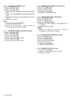
3.1.3.9
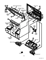
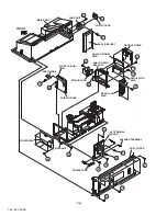
REMOVING THE REGULATOR PWB (Fig.5)
• Remove the LAMP COVER.
• Remove the BODY COVER.
• Remove the BODY BRACKET.
• Remove the MAIN UNIT.
• Remove the AV TERMINAL BOARD.
• Remove the REAR JACK PWB.
• Remove the PWB HOLDER.
• Remove the RECEIVER PWB.
(1) Remove the 4 screws
[U]
.
(2) Remove the REGULATOR PWB.
3.1.3.10 REMOVING THE DIGITAL SIGNAL PWB (Fig.5)
• Remove the LAMP COVER.
• Remove the BODY COVER.
• Remove the BODY BRACKET.
• Remove the MAIN UNIT.
• Remove the AV TERMINAL BOARD.
• Remove the PWB HOLDER.
(1) Remove the 1 screw
[V]
.
(2) Remove the EARTH WIRE.
(3) Remove the 1 screw
[W]
.
(4) Remove the DIGITAL SIGNAL PWB.
CAUTION :
•
Make sure to perform the "SYSTEM SETTEING" , when
DIGITAL SIGNAL PWB is replaced.
•
Especially, because the value of S039 (ILA COM) might
been changed, go through next steps to confirm the set-
ting value with the remote control unit.
(1)
Press [INFORMATION] key and [MUTING] key
simultaneously, to enter the SERVICE MODE.
(2)
Press [1] key to enter the ADJUSTMENT MODE.
(3)
Select [S039].
(4)
Confirm the value to "0", and set it to "0" when not
"0".
(5)
Press [MUTING] key, to memorize the data.
(6)
Press [BACK] key twice to exit the SERVICE MODE.


