START
STOP
DATE
PLAY
REW
REC
STOP
PAUSE
FF
TV/VCR CH
SP/EP
C. RESET
CANCEL
REVIEW
DBS
DAILY
WEEKLY
ENTER
REC
LINK
REC
SPEED
SKIP
SEARCH
MENU
BLANK
VCR
PROGRAM
PROG.CHECK
TIMER
A/B/C/D
TV
TV/VCR
CABLE
/DBS
POWER
REMOTE
CODE
AUX
TV
VOL
A.MO
NITOR
DISPLAY
OSD
ENTER
BACKK
1
2
3
4
5
6
7
8
0
9
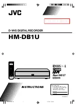
HM-DB1U
D-VHS DIGITAL RECORDER
INSTRUCTIONS
LPT0803-001A
For Customer Use:
Enter below the Model No. and
Serial No. which are located on the
rear of cabinet. Retain this
information for future reference.
Model No.
Serial No.
MTP
NTSC
HM-DB1U-EN01-09
21/11/03, 11:05 AM
1
暫定版
Version 3
2003.12.18


