1-10
1.10
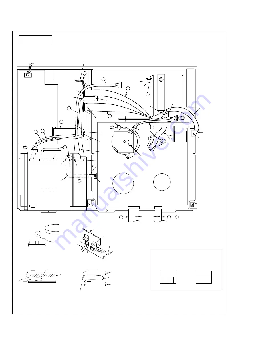
CONNECTION
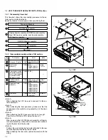
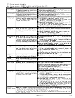
Fig. 1-10-1 Top view
TOP VIEW
Foil side
CN5301
(Lower)
Supporting
tape side
Supporting
tape side
Make a
crease.
Make a
crease.
Make a
crease.
Make a crease.
Foil side
Foil side
Foil side
Foil side
Treat the wire
according to the
figure not to
overlap in TP.
Treat wire so as not to come to the FAN motor.
Make a crease.
Supporting
tape side
Should be confirmed that wire
not touch to IC of the Stator
board assembly.
CN5323
(Middle)
CN5326
(Upper)
CN1
B
DRUM
HDD
CN8001
A
C
CN5325
CN5322
CN5321
CN5201
CN8901
CN8201
CN8202
CN8001
CN8002
CN8801
CN8601
CN703
CN7506
CN512
CN7508
CN2601
CN3001
CN2001
CN1
CN1
CON1
CN7509
CN3014
6
3
4
9
5
8
1
2
13
14
15
16
11
12
10
A/C HEAD
DRUM
FAN motor
B
D
CN3011
CN7507
7
CN3014
Main board
assembly
Main board assembly
Main board
assembly
Chassis
Absorb the looseness of
the wire in the B part.
Treat the front wires
according to the figure.
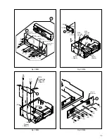
DETAIL "B"
Frame
Digital board
assembly
The wire should be
does not touch from edge.
The excessive length portion of
wire should be treat as figure.
DETAIL "D"
DETAIL "A"
DETAIL "C"
Base(1)
[CAUTION]
Insert the FPC wires as shown below.
Foil side
Supporting tape side
Supporting
tape side
Supporting
tape side
Supporting
tape side
Treat the wire
through the hole.
Foil side
Foil side
Foil side

