2-21
MECHANISM ADJUSTMENT (DV)
2.9 PREPARATION
2.9.1
Precautions
(1) Observe the specified screw tightening torque when at-
taching parts. The torque should be 0.04 Nm (0.4 kgfcm)
unless otherwise specified.
(2) Always disconnect the power supply unit before proceed-
ing to solder or attach parts.
(3) When plugging or unplugging a wire, be careful not to
damage the connector.
(4) When replacing a part, be careful not to damage other
parts or to mistakenly attach parts.
2.9.2
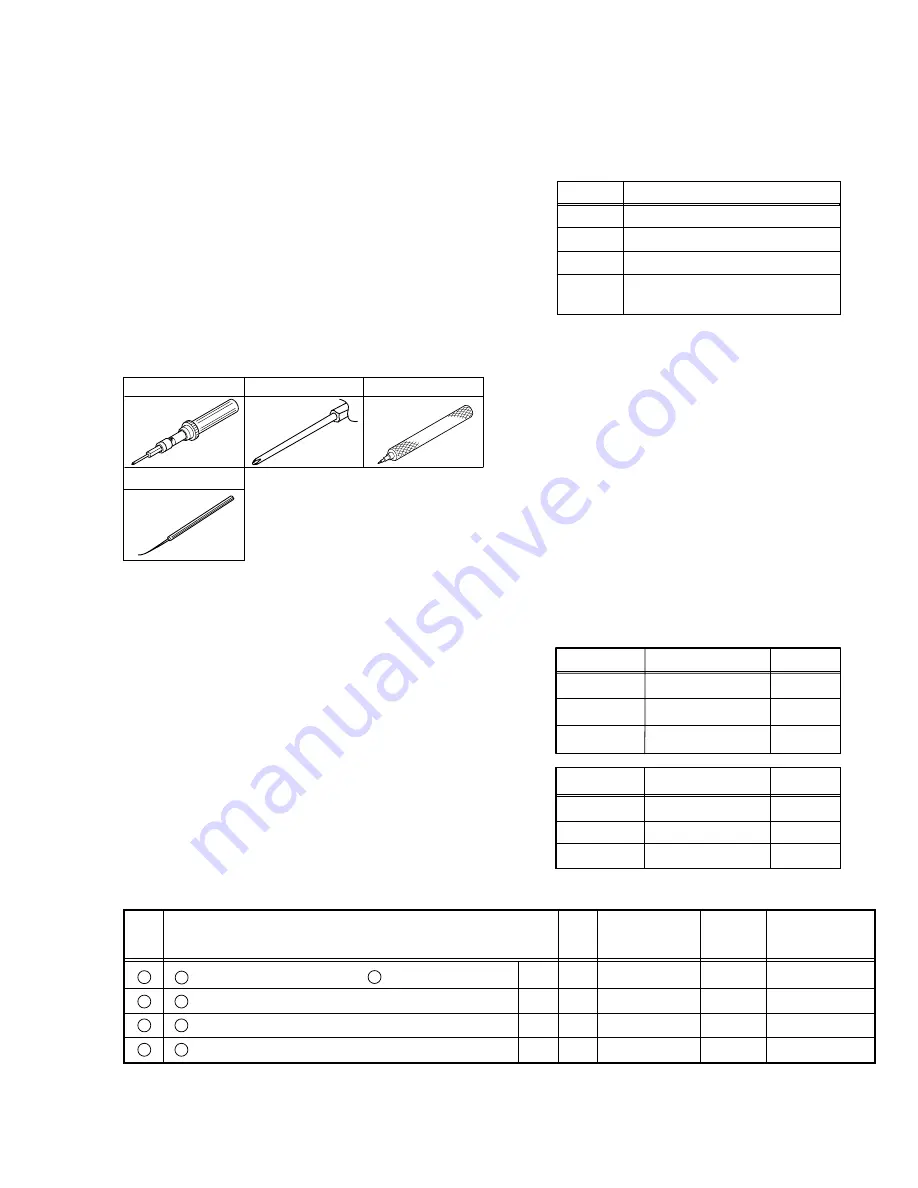
Tools Required for Adjustments
2.9.3
Disassembly and Assembly Procedures
The following table shows the steps for assembling or dis-
assembling the mechanism parts. Read the following descrip-
tions carefully before actual assembly/disassembly opera-
tions.
(1) : Order of disassembly steps. Reverse this order when
assembling.
(2) : Name of the disassembled/assembled part.
(3) : Surface where the disassembled/assembled part is
mounted. T = Top. B: Bottom.
(4) : Number of disassembly drawing.
Step
Fig.
/Loc
Part Name
No.
Point
Note
Discription
No.
1
A Cassette housing assembly/ B Mechanism assembly
T
1
2(S1),(L1) – (L5)
1
2
1 Drum assembly
T
2
3(S2)
2,3
3
2 Motor bracket assembly
T
2
4(S2)
2,4
4
3 Middle catcher assembly
T
3
3(S2)
—
§
§
§
§
§
§
§
(1)
(2)
(3)
(4)
(5)
(6)
(7)
(5) : Parts to be removed in disassembly/assembly, such as
screws, washers and springs, and the points.
Symbol
Name & Point
S
Screw
W
Washer
P
Spring
*
Connector, lock(L), soldering(SD),
shield, etc.
[Example] • (W1) = Remove the washer W1.
• (P1)
= Remove the spring P1.
(6) : Notes for disassembly/assembly.
(7) : For the phase alignment in disassembly/assembly and
the parts which require phase adjustments after assem-
bly, see “2.16 MECHANISM PHASE CHECK/ADJUST-
MENT”.
2.9.4 Screws and Washers Used in Disassembly/As-
sembly of the Mechanism Assembly
Table 2-9-1 shows the symbols, designs, part numbers and
colors of the screws and washers used in the mechanism
assembly.
When disassembling or assembling the mechanism assem-
bly, be sure to attach screws and washers correctly by refer-
ring to the following table.
Part number
(W1)
(W3)
YQ44246
YQ43933-2
Symbol
Part number
Symbol
(W2)
YQ44246-3
Color
RED
BLACK
BLACK
(S1)
(S2)
(S3)
QYTDSP2004Z
YQ43893-7
Color
GOLD
SILVER
BLACK
YQ43893
Table 2-9-2
Table 2-9-1 Tools Required for Adjustments
3
BIT
YTU94088-003
1
2
TORQUE DRIVER
YTU94088
Tool for installing slit washer
YTU94121A
Tool for replacing tip IC
PTS40844-2
4
Summary of Contents for HR-DVS2EK
Page 5: ......
Page 41: ...2 20 ...


