DISASSEMBLY INSTRUCTIONS
1-5
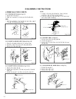
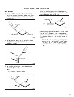
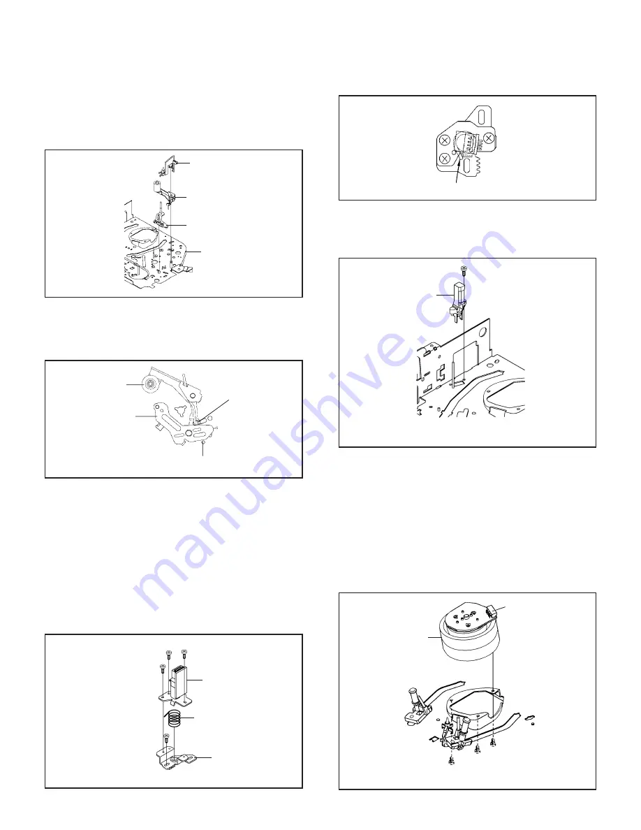
2-10: CASSETTE OPENER/PINCH ROLLER BLOCK/P5
ARM ASS’Y (Refer to Fig. 2-10-A)
1.
2.
Unlock the support
1
and remove the Cassette Opener.
Remove the Pinch Roller Block and P5 Arm Ass’y.
Fig. 2-10-A
Cassette Opener
1
Pinch Roller Block
P5 Arm Ass’y
Main Chassis
NOTE
1.
2.
Do not touch the Pinch Roller. (Use gloves.)
In case of the Pinch Roller Block and the Pinch Roller
Cam installation, install correctly as Fig. 2-10-B.
Fig. 2-10-B
Pinch Roller Block
Can be seen the hole of
the Pinch Roller Cam.
P5 Arm Ass’y
Can be seen the hole of the
Main Cam.
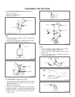
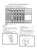
2-11: A/C HEAD (Refer to Fig. 2-11-A)
1.
2.
3.
4.
Remove the screw
1
.
Remove the A/C Head Base.
Remove the 3 screws
2
.
Remove the A/C Head and A/C Head Spring.
NOTE
1.
2.
3.
Do not touch the A/C Head. (Use gloves.)
When you install the A/C Head Spring, install as shown in
Fig. 2-11-B.
When you install the A/C Head, tighten the screw (1) first,
then tighten the screw (2), finally tighten the screw (3).
Fig. 2-11-A
(1)
2
A/C Head
A/C Head Spring
A/C Head Base
• Screw Torque: 5
±
0.5kgf•cm (Screw
1
)
2
2
(3)
(2)
1
Fig. 2-11-B
Spring Position
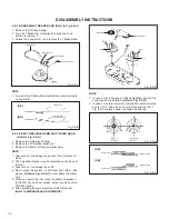
2-12: FE HEAD (RECORDER ONLY) (Refer to Fig. 2-12)
1.
2.
Remove the screw
1
.
Remove the FE Head.
Fig. 2-12
1
FE Head
• Screw Torque: 5
±
0.5kgf•cm
• The FE Head is not installed on the Video Cassette Player.
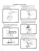
2-13: AHC ASS’Y/CYLINDER UNIT ASS’Y
(Refer to Fig. 2-13)
1.
2.
3.
Disconnect the following connector:
(CD2001)
Remove the 3 screws
1
.
Remove the Cylinder Unit Ass’y.
NOTE
1. When you install the Cylinder Unit Ass’y, tighten the
screws from (1) to (3) in order while pulling the Ass’y
toward the left front direction.
Fig. 2-13
Cylinder Unit Ass’y
1
(1)
• Screw Torque: 3
±
0.5kgf•cm
1
1
(2)
(3)
CD2001
Summary of Contents for HR-J6009UM
Page 2: ......
Page 6: ......
Page 54: ......
Page 55: ......
Page 56: ...VICTOR COMPANY OF JAPAN LIMITED VIDEO DIVISION Printed in Japan S40894 ...

