background image

4-3

<Reference>

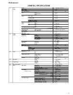
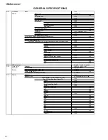
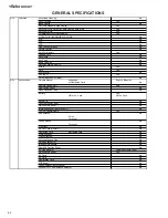
GENERAL SPECIFICATIONS

G-12

Remote

Unit

RC-ES

Control

Glow in Dark Remocon

No

Format type

JVC 

Custom Code

43 / 03

Power Source

Voltage(D.C)

3V

UM size x pcs

UM-4 x 2 pcs

Total Keys

35 Keys

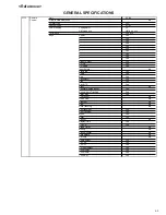
Keys

Power

Yes

1

Yes

2

Yes

3

Yes

4

Yes

5

Yes

6

Yes

7

Yes

8

Yes

9

Yes

0/Input Select

Yes

CH Up

Yes

CH Down

Yes

Input Select

No

Play/Slow

Yes

F.Fwd

Yes

Rew

Yes

Pause/Still Yes
Stop

Yes

Rec/OTR

Yes

Eject

No

Counter Reset/Cancel

Yes

Speed / Auto Tracking

Yes

Timer Rec

Yes

TV Monitor

No

Quick View

No

Program

No

Slow

No

Auto Tracking

No

Set/T

Yes

Set/ Tracking -

Yes

Menu

Yes

Enter

Yes

Cancel

No

Display(Call)

Yes

TV/VCR

Yes

Sleep Timer

No

Muting

No

Clock/Counter

No

Zero Return

No

CM Skip

No

Audio Select

Yes

TV CH+

Yes

TV CH-

Yes

TV Input Select

Yes

TV

Yes

TV Volume-

Yes

TV Power

Yes

Summary of Contents for HR-J6009UM

Page 1: ...ject to change without notice AC 110 V 220 V 50 Hz 60 Hz 10 W 2 0 W 5 C to 40 C 41 F to 104 F 20 C to 60 C 4 F to140 F Horizontal only 360 mm x 95 mm x 224 mm 3 2 kg VHS NTSC standard 210 min with ST 210 video cassette 630 min with ST 210 video cassette NTSC type color signal and E IA monochrome signal 525 lines 60 fields DA 4 Double Azimuth head helical scan system 42 dB 230 lines 100 Hz to 10 00...

Page 2: ......

Page 3: ...DJUSTMENT 1 17 1 1 SWITCHING POINT 1 17 ELECTRICAL ADJUSTMENT PARTS LOCATION GUIDE 1 17 IC DESCRIPTIONS 1 18 SERVO TIMING CHART 1 21 MECHANISM TIMING CHART 1 22 TROUBLESHOOTING GUIDE POWER DOES NOT TURN ON 1 23 POWER SHUTS OFF 1 24 CYLINDER NOT ROTATING DURING PLAYBACK AND RECODRDING 1 25 CASSETTE IN AND DOWN UNIT HAS NO FUNCTIONS 1 25 FF REW DO NOT WORK 1 26 AUDIO SHAKES 1 26 CASSETTE TAPE IS NOT...

Page 4: ...e specified for compliance with recognized codes pertaining to X ray emission Consequently when servicing these products replace the cath ode ray tubes and other parts with only the specified parts Under no circumstances attempt to modify these circuits Unauthorized modification can increase the high voltage value and cause X ray emission from the cathode ray tube 12 Crimp type wire connector In s...

Page 5: ...eter to measure across both terminals of load Z See figure 9 and following table 2 5 Grounding Class 1 model only Confirm specified or lower grounding impedance between earth pin in AC inlet and externally exposed accessible parts Video in Video out Audio in Audio out or Fixing screw etc Measuring Method Connect milli ohm meter between earth pin in AC inlet and exposed accessible parts See figure ...

Page 6: ......

Page 7: ...ig 1 2 1 2 Open Flap to 90 and flex in direction of arrow A at the same time slide in direction of arrow B Then lift in direction of arrow C 1 3 DECK CHASSIS Refer to Fig 1 3 1 2 3 Remove the 3 screws 1 Disconnect the following connectors CP1001 CP4001 CP4002 and CP4003 Remove the Deck Chassis in the direction of arrow Fig 1 2 Fig 1 3 A Flap B C 1 1 A 2 2 2 2 2 2 B 1 4 SYSCON PCB Refer to Fig 1 4 ...

Page 8: ...he Locker Spring Unlock the 4 supports 1 and then remove the Cassette Side L R Unlock the support 2 and then remove the Locker R Locker Spring Cassette Side L Cassette Side R Locker R Cassette Holder 1 1 1 1 2 In case of the Locker R installation check if the two positions of Fig 2 3 B are correctly locked When you install the Cassette Side R be sure to move the Locker R after installing NOTE 1 2 ...

Page 9: ...Remove the Tension Spring Unlock the 2 supports 1 and remove the Tension Band Unlock the support 2 and remove the Tension Arm Ass y Unlock the support 3 and remove the Tension Connect Float the hook 4 and turn it clockwise then remove the Tension Holder Fig 2 6 C Loading Motor Cassette Opener Fig 2 7 B Tension Band Tension Connect Tension Spring Tension Arm Ass y Tension Holder 1 1 3 2 4 NOTE 1 2 ...

Page 10: ...Reel and T Reel The Polyslider Washer may be remained on the back of the reel Take care not to damage the shaft Do not touch the section A of S Reel and T Reel Use gloves Refer to Fig 2 9 A Do not adhere the stains on it When you install the reel clean the shaft and grease it FG 84M If you do not grease noise may be heard in FF REW mode After installing the reel adjust the height of the reel Refer...

Page 11: ...NOTE 1 2 3 Do not touch the A C Head Use gloves When you install the A C Head Spring install as shown in Fig 2 11 B When you install the A C Head tighten the screw 1 first then tighten the screw 2 finally tighten the screw 3 Fig 2 11 A 1 2 A C Head A C Head Spring A C Head Base Screw Torque 5 0 5kgf cm Screw 1 2 2 3 2 1 Fig 2 11 B Spring Position 2 12 FE HEAD RECORDER ONLY Refer to Fig 2 12 1 2 Re...

Page 12: ...e met Refer to Fig 2 15 B And also can be seen the Main Chassis hole through the Main Cam maker hole Fig 2 15 B Pinch Roller Cam Marker Main Cam 2 16 LOADING GEAR S T UNIT Refer to Fig 2 16 A 1 2 Remove the E Ring 1 and remove the Main Loading Gear Remove the Main Rod Tension Lever Loading Arm S Unit and Loading Arm T Unit 1 Main Loading Gear Main Rod Tension Lever Loading Arm T Unit Loading Arm S...

Page 13: ...ss y installation install it with inserting the spring of the Clutch Ass y into the dent of the Coupling Gear Refer to Fig 2 17 B Fig 2 17 B Clutch Ass y Coupling Gear 2 18 CASSETTE GUIDE POST INCLINED BASE S T UNIT P4 CAP Refer to Fig 2 18 A 1 2 3 Remove the P4 Cap Unlock the support 1 and remove the Cassette Guide Post Remove the Inclined Base S Unit and Inclined Base T Unit Fig 2 18 A Cassette ...

Page 14: ...ring the IC leads completely Fig 3 2 Blower type IC desoldering machine IC 3 When IC starts moving back and forth easily after desoldering completely pickup the corner of the IC using a tweezers and remove the IC by moving with the IC desoldering machine Refer to Fig 3 3 NOTE Some ICs on the PCB are affixed with glue so be careful not to break or damage the foil of each IC leads or solder lands un...

Page 15: ...ld Wire Refer to Fig 3 7 NOTE Do not absorb the solder to excess Fig 3 7 Soldering Iron IC Braided Shield Wire 4 When bridge soldering between terminals and or the soldering amount are not enough resolder using a Thin tip Soldering Iron Refer to Fig 3 8 Fig 3 8 Thin tip Soldering Iron IC 5 Finally confirm the soldering status on four sides of the IC using a magnifying glass Confirm that no abnorma...

Page 16: ...Flipflop Frequency Generator Front Loading Switch Frequency Modulation Frequency Sub Carrier Forward Generator Ground High Pass Filter I K L M N O P R S H SW Hz IC IF IND INV KIL L LED LIMIT AMP LM LDM LP L P F LUMI M MAX MINI MIX MM MOD MPX MS SW NC NR OSC OPE PB PB CTL PB C PB Y PCB P CON PD PG P P R REC REC C REC Y REEL BRK REEL S REF REG REW REV RVS RF RMC RY S CLK S COM S DATA SEG SEL SENS SE...

Page 17: ...eparator Separation Transistor Tracking Trick Playback Test Point Unregulated Volt Voltage Controlled Oscillator Video Intermediate Frequency Vertical Pulse Voltage Display Video Playback Variable Resistor Video Recording Visual Search Fast Forward Visual Search Rewind Voltage Super Source Vertical Synchronization Voltage Tuning Crystal Luminance Chrominance ...

Page 18: ...G SYSTEM When cleaning the tape transport system use the gauze moistened with isopropyl alcohol 3 CYLINDER Wrap a piece of chamois around your finger Dip it in isopropyl alcohol Hold it to the cylinder head softly Turn the cylinder head counterclockwise to clean it in the direction of the arrow Refer to the figure below NOTE Do not exert force against the cylinder head Do not move the chamois upwa...

Page 19: ...ng PLAY Adjusting of the Tracking to the center position Refer to the MECHANICAL ADJUSTMENT GUIDE ROLLER and ELECTRICAL ADJUSTMENT SWITHCHING POINT Make the short circuit between the test point of SERVICE and the GND The BOT EOT and the Reel Sensor do not work and the deck can be operated without a cassette tape Refer to the PREPARATION FOR SERVICING MECHANISM ADJUSTMENT PARTS LOCATION GUIDE 1 2 3...

Page 20: ...ACK TENSION TORQUE DURING PLAYBACK 1 2 3 After confirmation and adjustment of Tension Post position Refer to item 1 1 load the cassette type torque tape and set to the PLAY mode Confirm that the right meter of the torque tape indicates 50 90gf cm during playback in SP mode Confirm that the left meter of the torque tape indicates 25 40gf cm during playback in SP mode 1 3 CONFIRMATION OF VSR TORQUE ...

Page 21: ...Brake Spring T Brake Arm 1 4 2 CONFIRMATION AND ADJUSTMENT OF TAPE RUNNING MECHANISM Tape Running Mechanism is adjusted precisely at the factory Adjustment is not necessary as usual When you replace the parts of the tape running mechanism because of long term usage or failure the confirmation and adjustment are necessary 2 1 GUIDE ROLLER 1 2 3 4 5 6 7 Playback the VHS Alignment Tape MHP Connect CH...

Page 22: ...mm 2 3 TAPE RUNNING ADJUSTMENT X VALUE ADJUSTMENT 1 2 3 4 5 6 Confirm and adjust the position of the Tension Post Refer to item 1 1 Adjust the Guide Roller Refer to item 2 1 Confirm and adjust the Audio Control Head Refer to item 2 2 Connect CH 1 of the oscilloscope to TP1002 CH 2 to TP4001 and CH 3 to HOT side of Audio Out Jack Playback the VHS Alignment Tape MHP Press and hold the Tracking Auto ...

Page 23: ...POINT CONDITIONS MODE PLAYBACK Input Signal Alignment Tape MHP INSTRUCTIONS Connect CH 1 on the oscilloscope to TP1002 and CH 2 to TP4201 Playback the alignment tape MHP Press and hold the Tracking Auto button on the remote control more than 2 seconds to set tracking to center Adjust the VR1001 until the waveform of the oscilloscope measures 6 5 0 5 H at both leading and trailing edges Refer to Fi...

Page 24: ...eset signal 17 P74 GND IN Ground 18 P73 IIC CLK OUT CLOCK terminal for IIC BUS communication 19 P72 IIC DATA OUT IN DATA terminal for IIC BUS communication 20 P71 Y C CS OUT Control terminal for Y C selection 21 P70 CAP_FULL OUT Output the HIGH during the acceleration force of capstan motor at SLOW mode 22 VDD VDD Power of CPU 23 AUDIO_FF HI FI H SW OUT Output terminal of HI FI Head SW 24 VIDEO_FF...

Page 25: ...FSC_IN 4FSC_IN IN 4 FSC pulse 54 SYNC SYNC IN Input terminal for composite SYNC 55 P67 Vsync POWER_OFF_L OUT 4FSC_MUTE control output of power off 56 P66 YC01 V_REC_ST H OUT On control of A V recording Whole width erase circuit 57 P65 YE01 2 4 HEAD IN The initial settings of 2 head or 4 head 58 P64 YC02 TUNER L OUT Output low at tuner and output high at external input play 59 P63 YE02 A MUTE H OUT...

Page 26: ...30 IRQ0 POWER_FAIL IN Input terminal of Power fail signal 90 P23 AC 32KHz IN The initial setting that is whether it does with subclock pulse or it does the counting of the clock with an AC pulse 91 P22 SP L OUT Tape speed SP mode at the time of LOW 92 P21 EP L OUT Tape speed EP mode at the time of LOW 93 P20 AUDIO_OUT_MUTE OUT L for at AUDIO MUTE and POWER OFF H for except above case 94 P17 PWM14 ...

Page 27: ...O TIMING CHART SYSCON PCB IC1001 OEC0115A DPG 39 PIN DFG 38 PIN H SW P 24 PIN V SYNC E E 54 PIN 24 Cycle CH 1 CH 2 REC CTL REC 35 PIN V SYNC TRICK PB 27 PIN WAVEFORM CHANGES DEPENDED ON THE TAPE SPEED 1 21 ...

Page 28: ... LEVER S BRAKE HIGH S BRAKE LOW BRAKE ON BRAKE ON BRAKE ON BRAKE ON CLUTCH LEVER CLUTCH ON DIRECT PRESS UP MECHANISM TIMING CHART TENSION CONNECT LINK UNIT S REEL BRAKE SENSOR MODE MS 1 LOW FF REW STOP2 FLAP LEVER T REEL BRAKE T BRAKE ARM HIGH LOW MS 2 S REEL BRAKE TENSION ARM ASS Y 323 8 303 7 272 2 226 4 HIGH 38 5 35 29 5 21 5 PB F SLOW 26 5 255 VSR 18 0 206 3 100 Revolutional Angle of MAIN CAM ...

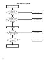
Page 29: ...E Is the voltage at cathode of D512 about 5V No Yes No Yes Check IC1001 Check AT 5 2V line and the check peripheral circuit Check Around T501 POWER DOES NOT TURN ON Is the voltage at pins 15 and 22 of IC1001 about 5V 1 23 ...

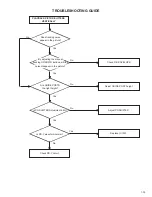
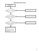
Page 30: ...nds Does it Power off in about 6 seconds Does it Power off intermittently POWER SHUTS OFF Insert a cassette and push PLAY button Yes No No No Yes Yes Check REEL SENSOR and CAPSTAN BELT Check REEL SENSOR and CAPSTAN BELT slack Check CAPSTAN DD UNIT and CYLINDER UNIT 1 24 ...

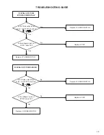
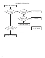
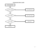
Page 31: ...C1001 lines Is the voltage at pins 11 and 12 of CP1001 about DC5V In playback is the voltage at pins 1 4 5 and 9 of CP1001 about DC5V 1 25 Check Operation PCB CASSETTE IN AND DOWN UNIT HAS NO FUNCTIONS Does mode OSD appear in Monitor No Yes Check LOADING MOTOR MODE SENSOR and the peripheral parts Does VCR operate with the remote control Yes No Check IC1001 ...

Page 32: ...O BLOCK Is AUDIO HEAD scratched No Yes No Yes No Yes Does pin 40 of IC1001 output about 5Vp p In playback is the voltage at pin 5 of CP1001 3 0V 1 26 Yes FF REW DO NOT WORK No Check DECK MECHANISM Check pins 8 and 9 of IC1001 lines Is the voltage changing at pin 82 of IC1001 when you press FF REW ...

Page 33: ...es No When cassette is not inserted is the voltage at pin 3 of IC1001 5V Check LED and PHOTO SENSOR on DECK Check circuit of LOADING MOTOR Replace IC1001 Does WORM GEAR activate When a cassette is inserted is the voltage between pins 2 and 8 of CP1001 12V When a cassette is inserted is the voltage at pin 63 of IC1001 5V 1 27 ...

Page 34: ...WHEN INSERTING CASSETTE IT EJECTS IMMEDIATELY Does Another cassette go down No Yes Defective CASSETTE or CASSETTE LOADING BLOCK No Yes No Yes Are SW1001 and the lever of the stage set correctly After a CASSETTE is inserted is the voltage at pin 80 of IC1001 LOW 1 28 ...

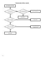
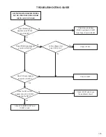
Page 35: ... UNREG 5V Yes Yes Check pins 26 38 39 and 65 of IC1001 lines Replace CYLINDER UNIT No Yes No Yes Replace IC1001 Check REEL SENSOR Replace CAPSTAN DD UNIT Yes No No In playback is the voltage at pins 1 4 5 and 9 of CP1001 about 5V No Does TP1002 feed HEAD SWITCHING PULSE signal Does PG PULSE signal appear at pin 39 of IC1001 1 29 ...

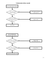
Page 36: ...ge at pin 1 of CP1001 12V CAPSTAN DD MOTOR NOT ROTATING Yes No Check POWER circuit Yes Yes Is the voltage at pin 3 of CP1001 5V In playback check the voltage at pin 25 of IC1001 is 2 5V Replace IC1001 Does DD MOTOR rotate now If not replace DD MOTOR 1 30 ...

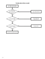
Page 37: ...at pin 83 of IC1001 about 5V Replace IC1001 Replace CYLINDER MOTOR No No PLAYBACK PICTURE SHAKES Yes Yes Replace CYLINDER MOTOR Is the voltage at pin 4 of CP1001 about 6V Replace IC1001 Replace CYLINDER MOTOR Is FG Pulse output level at pin 1 of CP1001 about 6V Is FG Pulse output level at pin 1 of CP1001 about 6V 1 31 ...

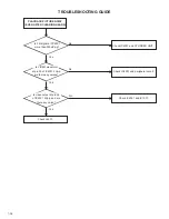
Page 38: ...eck peripheral circuit Check Q1002 Does the REEL SENSOR PULSE signal appear at pin 87 and IC1001 AUTO TRACKING DOES NOT OPERATE Yes No Check CYLINDER UNIT Yes No Yes In auto tracking is the voltage at pin 14 of IC1001 more than DC1 65V Replace IC1001 Check CONTROL HEAD By manual tracking does the DC level at pin 59 of IC4001 change No Does the CTL PULSE about 1 0Vp p appear at pin 37 of IC1001 1 0...

Page 39: ...oes tracking noise appear in the picture Yes No Yes No Yes Yes Check P B ENVELOPE Are GUIDE POSTS the right height Is PG SHIFTER Adjustment 6 5H Replace IC1001 Yes Is PB Y waveform normal Check PB Y circuit No No By adjusting the manual tracking UP DOWN buttons will the noise disappear in the picture 1 33 ...

Page 40: ...itor TV Yes No Yes Yes Yes No Is the voltage at pins 44 52 and 68 of IC4001 5V Check P CON 5V line Check IC4001 Is there Video signal at pin 30 of IC4001 Check J4203 Is there VIDEO signal at pin 26 of IC4001 Check IC4001 and the peripheral circuit Check J4201 No No 1 34 ...

Page 41: ...cuit Is there Color signal in Video signal at pin 26 of IC4001 Yes No Replace IC4001 Check IC4001 No NO COLOR DURING SELF RECORDING AND PLAYBACK Does VIDEO signal appear at pin 30 of IC4001 Yes No Replace J4203 Check VIDEO input circuit Yes Does VIDEO signal appear at pin 26 of IC4001 Change IC4001 Check IC4001 and peripheral circuit 1 35 ...

Page 42: ...t TP4001 more than 300mVp p No Yes No No Yes Yes Check IC4001 and CYLINDER UNIT Check IC4001 and peripheral circuit Check IC4001 and IC1001 Check J4201 Is VIDEO waveform at pin 30 of IC4001 2Vp p are there any noises Is video output at pin 26 of IC4001 2Vp p and are there any noise 1 36 ...

Page 43: ...ction NO E E Does AUDIO signal appear at pin 6 of IC4001 Yes Yes Check C4031 and peripheral circuit Does AUDIO signal appear at pin 10 of IC4001 Check IC4001 and peripheral circuit Check AUDIO HEAD for debris of stains Check that the connector from AUDIO HEAD is fully inserted to Replace IC4001 1 37 ...

Page 44: ... IC4001 T4001 is broken or shorted Yes No Is there AUDIO signal at pin 10 of IC4001 Check J4201 and peripheral circuit Check the circuit between audio out of Tuner and pin 10 of IC4001 No Yes Is BIAS level O K at T4001 60V Is the voltage at Emitter of Q4003 5V Check POWER circuit Yes Yes No No 1 38 ...

Page 45: ...26 of IC4001 Check the circuit from VIDEO input jack to IC4001 from Tuner Pack to IC4001 Yes Is the voltage at pin 56 of IC1001 5V Check IC1001 Does FM signal appear at pin 59 to IC4001 Yes No Check IC4001 No Yes Does the FM current appear at pin 59 of IC4001 during the REC Check IC4001 and check the peripheral circuit Check CYLINDER UNIT and IC4001 circuit No Yes No No Yes 1 39 ...

Page 46: ...connect the plugs from the VIDEO input Jacks No Yes No Yes Check peripheral circuit Check VIDEO No Yes Does VIDEO signal appear at pin 24 of TU6001 Replace TU6001 Is there VIDEO waveform at pin 32 of IC4001 Check J4201 Replace IC4001 Do the voltages appear at each terminal B 5V PB 5V and TU 32V of TU6001 1 40 ...

Page 47: ...AUDIO MONO Is the voltage at pins 52 68 and 77 of IC4001 5V Check POWER BLOCK Check J4204 and J4205 Replace IC4001 Check J4201 Does signal appear at pin 10 of IC4001 Does signal appear at pin 78 of IC4001 No Yes Yes No Yes No 1 41 ...

Page 48: ...Does signal appear at pin 22 of TU6001 Check TU6001 and peripheral circuit Does signal appear at pin 76 of IC4001 Replace IC4001 Check J4201 and peripheral circuit No Yes Yes No Yes No Do the voltages appear at each terminal B 5V PB 5V and TU 32V of TU6001 1 42 ...

Page 49: ...MHz Preset CH No RF Converter Output Yes Channel 3 or 4 ch Level Impedance 66dBu 75ohm Sound Selector No Stereo Dual TV Sound Yes US ST G 3 Power Power Source AC 110 220V 50 60Hz DC Power Consumption Power On at AC 10 W at 220V 60Hz Stand by at AC 2 0 W at 220V 60Hz Per Year kWh Year Protector Power Fuse Yes Dew Sensor No G 4 Regulation Safety NOM IEC65 Radiation CISPR13 G 5 Temperature Operation ...

Page 50: ...s Pin Code No Tape Counter Yes Index No Hotel Lock No Tape Speed Yes Manual Tracking Bar Setting No Hi Fi Yes S Repeat SR R SR Play No VPS No PDC No G 9 OSD Language English French Spanish G 10 Clock Timer Calendar 1990 1 1 2081 12 31 and Timer Timer Events 8 prog 1 month Back up One Touch Recording Max Time 5 Hours OTPB Valid Time No Timer Back up at Power Off Mode 18 Hours G 11 Display Indicator...

Page 51: ... Yes CH Down Yes Input Select No Play Slow Yes F Fwd Yes Rew Yes Pause Still Yes Stop Yes Rec OTR Yes Eject No Counter Reset Cancel Yes Speed Auto Tracking Yes Timer Rec Yes TV Monitor No Quick View No Program No Slow No Auto Tracking No Set Tracking Yes Set Tracking Yes Menu Yes Enter Yes Cancel No Display Call Yes TV VCR Yes Sleep Timer No Muting No Clock Counter No Zero Return No CM Skip No Aud...

Page 52: ...ssories Owner s Manual Language English Spanish w Guarantee Card No Remote Control Unit Yes Dew Cation Sheet No Video Cassette Tape No Battery Yes UM size x pcs UM 4 x 2pcs Safety Tip No Toll Free Insert Sheet No Quick Set Up Sheet No Information Sheet Buyer Supply No 75 Ohm Coaxial Cable Yes Rod Antenna No Poles Terminal Loop Antenna No Terminal U V Mixer No DC Car Cord Center No Guarantee Card w...

Page 53: ...deo Input No Audio Input No Video Output RCA x 1 Yellow Audio Output RCA x 2 White Red Euro Scart No DC Jack 12V Center No VHF UHF Antenna Input Output F Type AC Inlet No G 16 Set Size Approx W x D x H mm 360 x 224 x 95 G 17 Weight Net Approx 3 2kg 7 1lbs Gross Approx 3 8kg 8 4lbs G 18 Carton Master Carton No Content Material Dimensions W x D x H mm Description of Origin Gift Box Yes Material Sing...

Page 54: ......

Page 55: ......

Page 56: ...VICTOR COMPANY OF JAPAN LIMITED VIDEO DIVISION Printed in Japan S40894 ...

Reviews: